Display Device Mounted in Working Vehicle and Display Method For the Display Device

Inactive Publication Date: 2009-01-08
KOMATSU LTD
View PDF2 Cites 35 Cited by
  • Summary
  • Abstract
  • Description
  • Claims
  • Application Information

AI Technical Summary

Benefits of technology

[0018]The display device according to the invention has the foregoing configuration. Accordingly, if the malfunction detection means detects a malfunction of the working vehicle when an image captured by the camera is displayed on the monitor screen by the second display means, the warning display means can superpose and display warning information on a part of the monitor screen. Thus, superposing and displaying the warning information on a part of the monitor screen in response to the detection of the malfunction in the working vehicle makes an operator viewing an image captured by the camera aware of a malfunction that has occurred in the working vehicle. Since an image captured by the camera as a result of input from the second display means can be continuously displayed on the monitor screen as it is even if a malfunction occurs, an operator operating the working vehicle is not hindered from checking safety.
[0019]Further, in the display device of the present invention, when the operation detecting means detects that the working vehicle has stopped working after the superposing and displaying of the warning information on a part of the monitor screen, image information input by the second switch means and displayed on the monitor screen can be automatically switched to image information input by the first display means, specifically, image information corresponding to information about the state of the working vehicle. According to this invention, after the working vehicle has stopped working, the display on the monitor screen can be switched to image information about the state of the working vehicle. This securely ensures the safety of the working vehicle and enables an operator to ascertain the cause/causes of a malfunction of the working vehicle unhurriedly.
[0020]In the display device of the present invention, the warning display means may further include sound generating means that generates a warning sound. T

Problems solved by technology

In such a working vehicle, since an operator sitting in an operator's cab has a wide field of view in front of the operator's cab, the operator can easily notice obstacles or the like existing in front of the working vehicle.
However,

Method used


Image

  • Display Device Mounted in Working Vehicle and Display Method For the Display Device
  • Display Device Mounted in Working Vehicle and Display Method For the Display Device
  • Display Device Mounted in Working Vehicle and Display Method For the Display Device

Examples


Example

EXPLANATION OF REFERENCE NUMERALS

[0029]1 display device[0030]2 camera[0031]3 monitor screen[0032]4 first switching switch[0033]5 warning buzzer[0034]6 controller[0035]7 sensor[0036]8 work machine lever[0037]9 running lever[0038]10 function key[0039]11 engine cooling water temperature meter[0040]12 oil pressure indicator[0041]13 fuel meter[0042]14 clock[0043]15 caution icon[0044]16 icon indicating cause of malfunction[0045]17 warning information (warning icon)

BEST MODE FOR CARRYING OUT THE INVENTION

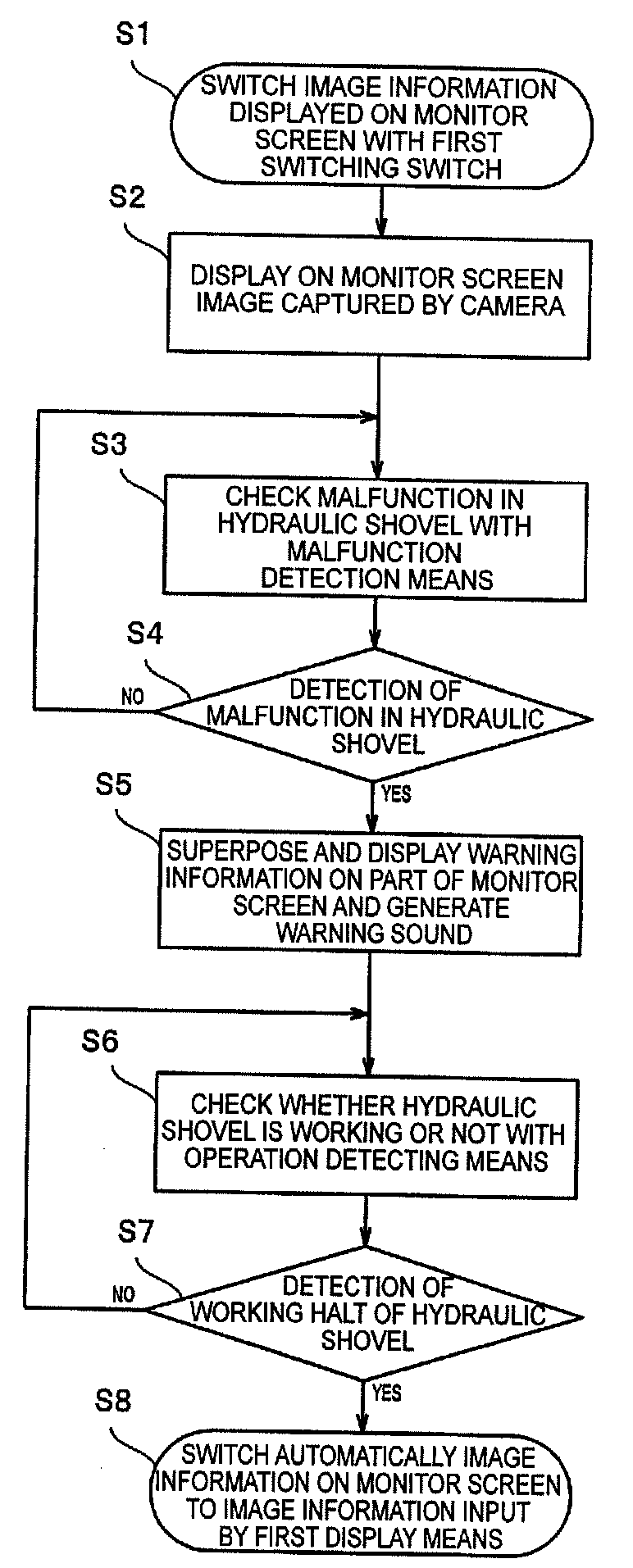
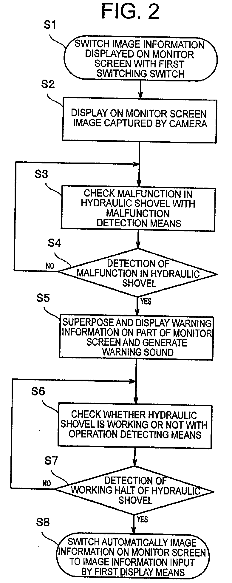
[0046]Referring to the accompanying drawings, an embodiment of a display device according to the invention will now be described in detail. The description below exemplifies a display device mounted in a hydraulic shovel, which is one type of working vehicle. However, the display device according to the invention is not limited thereto but can also be mounted in any other working vehicle.

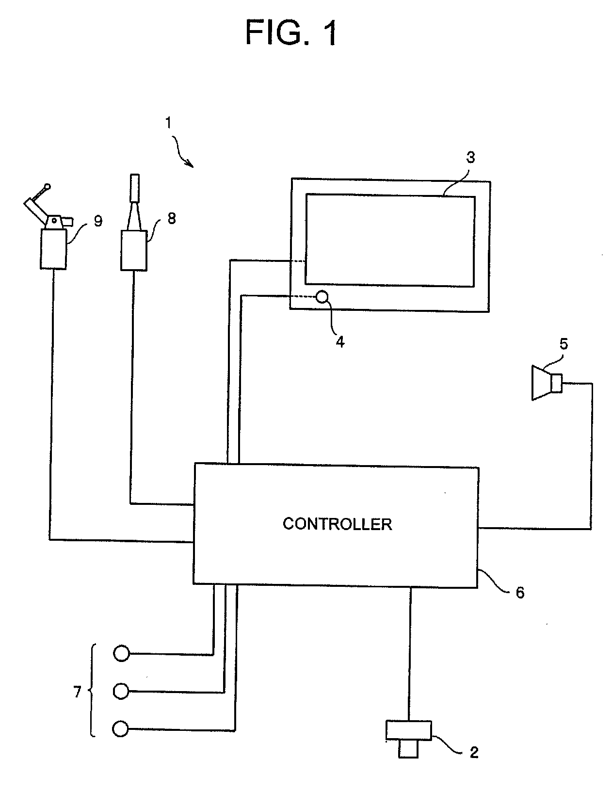
[0047]FIG. 1 is a block diagram showing the configuration of a display device according to the inventio...


PUM


Abstract

A display device is mounted in a working vehicle equipped with a camera that monitors areas around the working vehicle. The display device includes: a monitor screen; first display means for displaying information about the working vehicle; second display means for displaying an image captured by the camera; first switching means for switching displayed image information; malfunction detection means for detecting a malfunction occured in the working vehicle; warning display means for displaying warning information; operation detecting means for detecting whether the working vehicle is working; and second switching means for automatically switching the image information displayed to the image information input by the first display means, where each referenced display is on the monitor screen. Thus, even if a malfunction occurs in the working vehicle, an operator is made aware of the malfunction in the working vehicle without being hindered from undertaking work while checking the safety.

Description

TECHNICAL FIELD[0001]The present invention relates to display devices mounted in working vehicles, such as a hydraulic shovel, and display methods for the display devices. More particularly, the invention relates to a display apparatus mounted in a working vehicle equipped with a camera that monitors areas around the working vehicle, the display device being designed such that images captured by the camera are displayed on the monitor screen of the display device, thereby enabling an operator of the working vehicle to confirm the safety, and also relates to a display method for such a display device.BACKGROUND ART[0002]Working vehicles such as a hydraulic shovel mainly comprise: an undercarriage freely movable in a particular direction; an upper rotating body placed on the undercarriage so as to be rotatable; and a work machine (i.e., front attachment) attached to the upper rotating body so as to be freely moved upward or downward. At the front of the upper rotating body is an opera...

Claims


Application Information

Patent Timeline
IPC IPC(8): E02F9/26
CPCB60R1/00B60R2300/207E02F9/26B60R2300/8093E02F9/24B60R2300/302B60R16/02E02F9/16
Inventor DATE, KAZUAKIKUWAHARA, TOSHIRO
Owner KOMATSU LTD
Why Eureka
Try Eureka