Shifting range sensing apparatus

US20110137534A1Active Publication Date: 2011-06-09HYUNDAI MOTOR CO LTD +2
4 Cites 11 Cited by

Patent Information

Authority / Receiving Office
US · United States
Current Assignee / Owner
Publication Date
2011-06-09

Smart Images

  • Figure 1
    Figure 1
  • Figure 2
    Figure 2
  • Figure 3
    Figure 3
Patent Text Reader

Abstract

A shifting range sensing system, may include a shift lever pivotally connected to a vehicle body, a shift range sensing apparatus to sense a pivotal movement of the shift lever, an inhibitor switch mounted in a transmission, and a controller taking an emergency measure when a signal of the inhibitor switch and a signal of the shifting range sensing apparatus do not indicate the same shifting range.
Need to check novelty before this filing date? Find Prior Art

Description

CROSS-REFERENCE TO RELATED APPLICATIONS

[0001] The present application claims priority to Korean Patent Application Number 10-2009-0119032 filed Dec. 3, 2009, the entire contents of which application is incorporated herein for all purposes by this reference.BACKGROUND OF THE INVENTION

[0002] 1. Field of the Invention

[0003] The present invention relates to a shifting range sensing apparatus, in more detail, an apparatus for detecting the current shifting range from the operation of a shifting lever.

[0004] 2. Description of Related Art

[0005] In automatic transmission vehicles of the related art, operational force of a shift lever that is operated by a driver is transmitted to an inhibitor switch and a manual valve of a valve body in the automatic transmission through a cable.

[0006] Accordingly, even it the inhibitor switch transmits incorrect information due to a failure, the manual valve mechanically receives the operational force of the shift lever and operates, such that the vehicle could ...

Examples

Embodiment Construction

[0032]Reference will now be made in detail to various embodiments of the present invention(s), examples of which are illustrated in the accompanying drawings and described below. While the invention(s) will be described in conjunction with exemplary embodiments, it will be understood that present description is not intended to limit the invention(s) to those exemplary embodiments. On the contrary, the invention(s) is / are intended to cover not only the exemplary embodiments, but also various alternatives, modifications, equivalents and other embodiments, which may be included within the spirit and scope of the invention as defined by the appended claims.

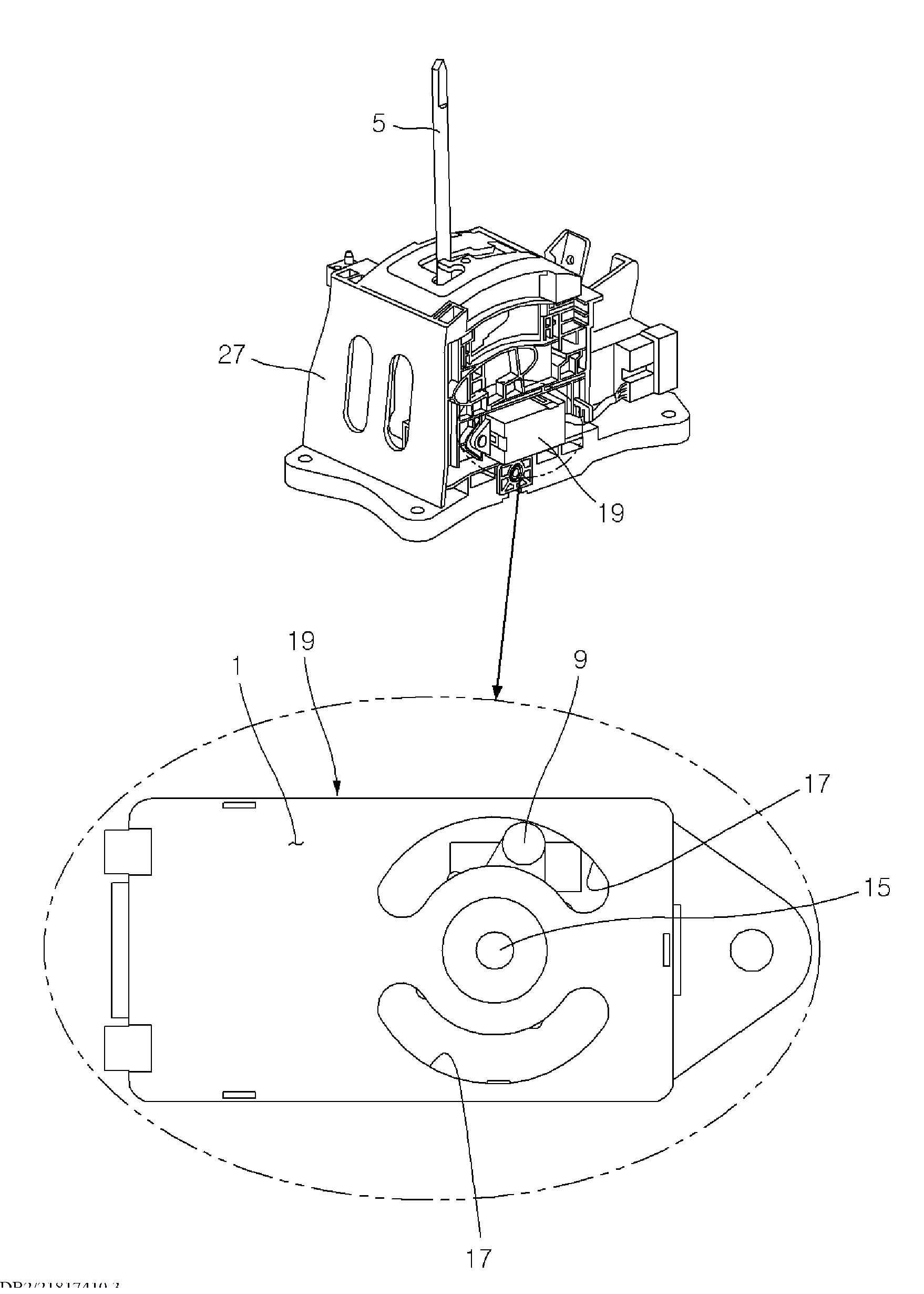
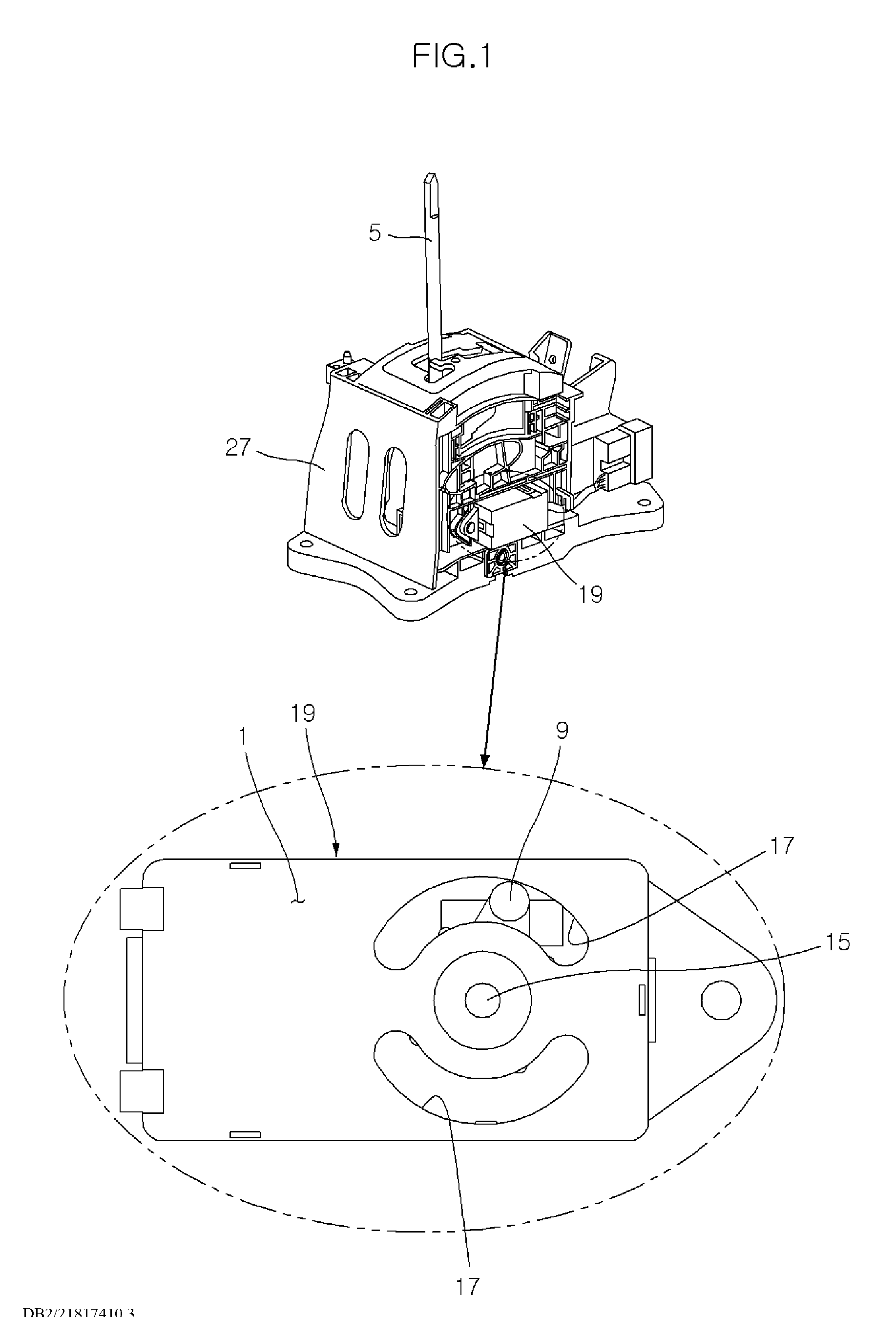
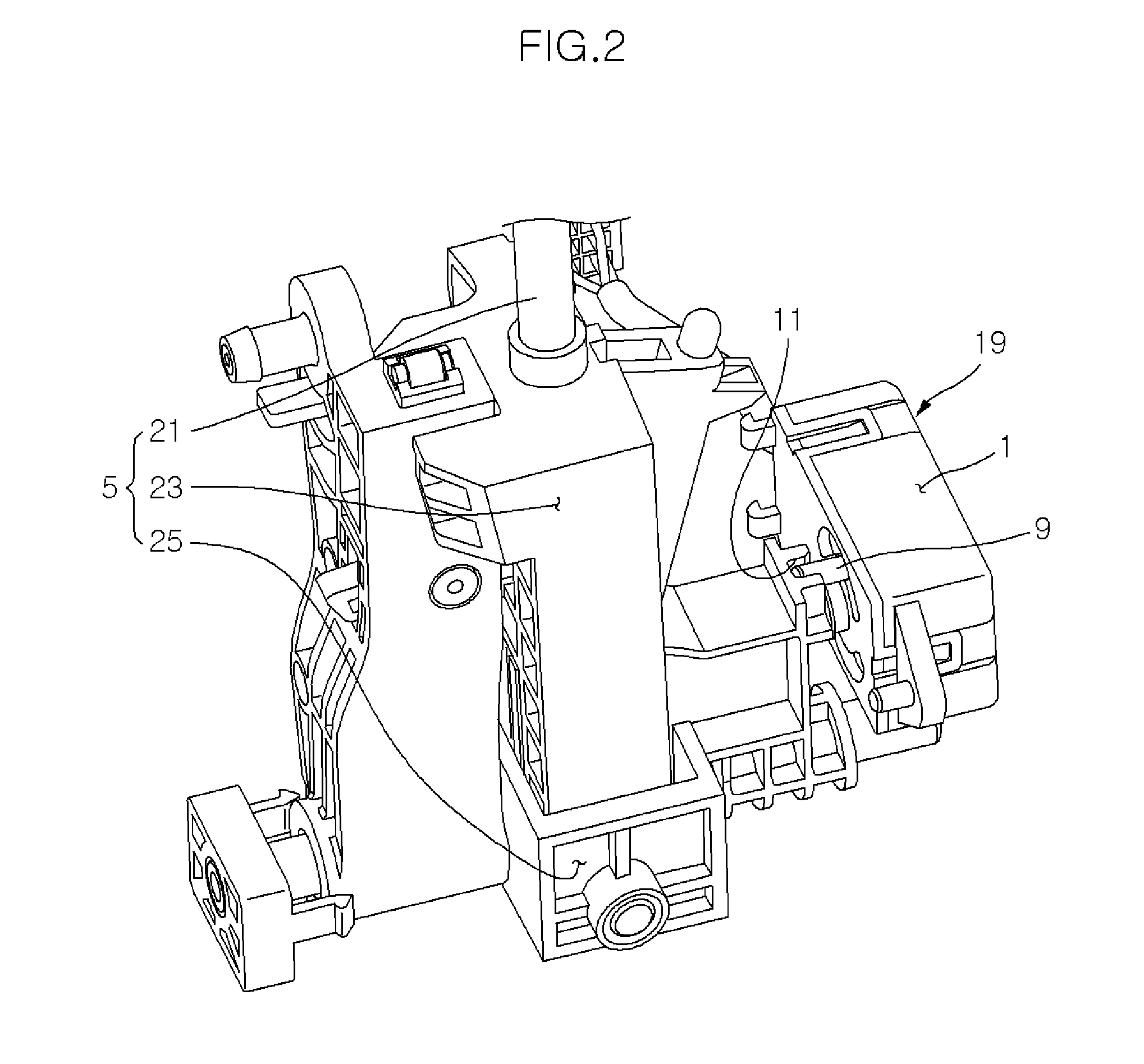
[0033]Referring to FIGS. 1 to 7, an embodiment of the present invention includes a housing 1 fixed with respect to a vehicle body, a magnet 3 rotatably disposed in housing 1, a power transfer unit transmitting rotation of shift lever 5 to rotation of magnet 3 in accordance with the rotational state of shift lever 5 such that magnet 3 ...