
Free-of-bearing rotational positioning device for a dewatering basket of a non-treading type wringer bucket

Inactive Publication Date: 2011-07-21
TUO SHEN INT
View PDF2 Cites 11 Cited by
  • Summary
  • Abstract
  • Description
  • Claims
  • Application Information

AI Technical Summary

Benefits of technology

[0009]An object of the invention is to provide a non-treading type wringer bucket that ensures the safety in use since the treading action is not necessary for the operation thereof. Moreover, the dewatering basket won't be loosened after an easy DIY-assembly (do-it-yourself).
[0010]Another object of the invention is to provide a wringer bucket having a simple structure and low production cost. The dewatering basket does not require a bearing while a smooth operation is still ensured for a long service life.
[0011]A further object of the invention is to provide a wringer bucket that may be stacked on each other for a convenient storage and transportation. Accordingly, less space will be occupied and the freight is considerably reduced.
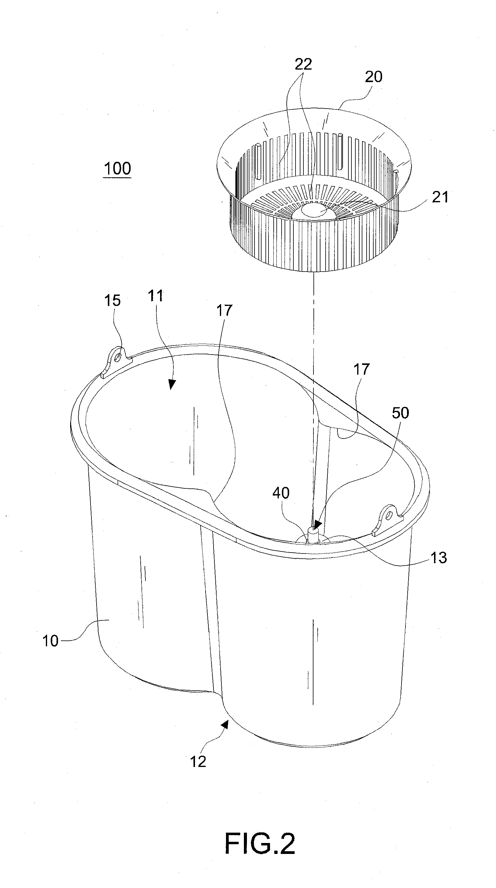
[0018]whereby the driven seat tends to slip from top to bottom over the connection part of the support shaft, and after the lower sleeve passes through positioning element in a compression manner, the positioning surface of the positioning element is stretched into the engagement groove when returning to its original shape; in this way, the dewatering basket can be protected from loosening from the support shaft when rotated thereon; moreover, the end stop of the upper sleeve lies against the top portion of the support shaft, thus creating a rotating center; thus, the whole contact point of the dewatering basket is concentrated at the rotating center, thereby reducing the frictional resistance between the shaft holder and the support shaft and therefore permitting a smooth rotation.
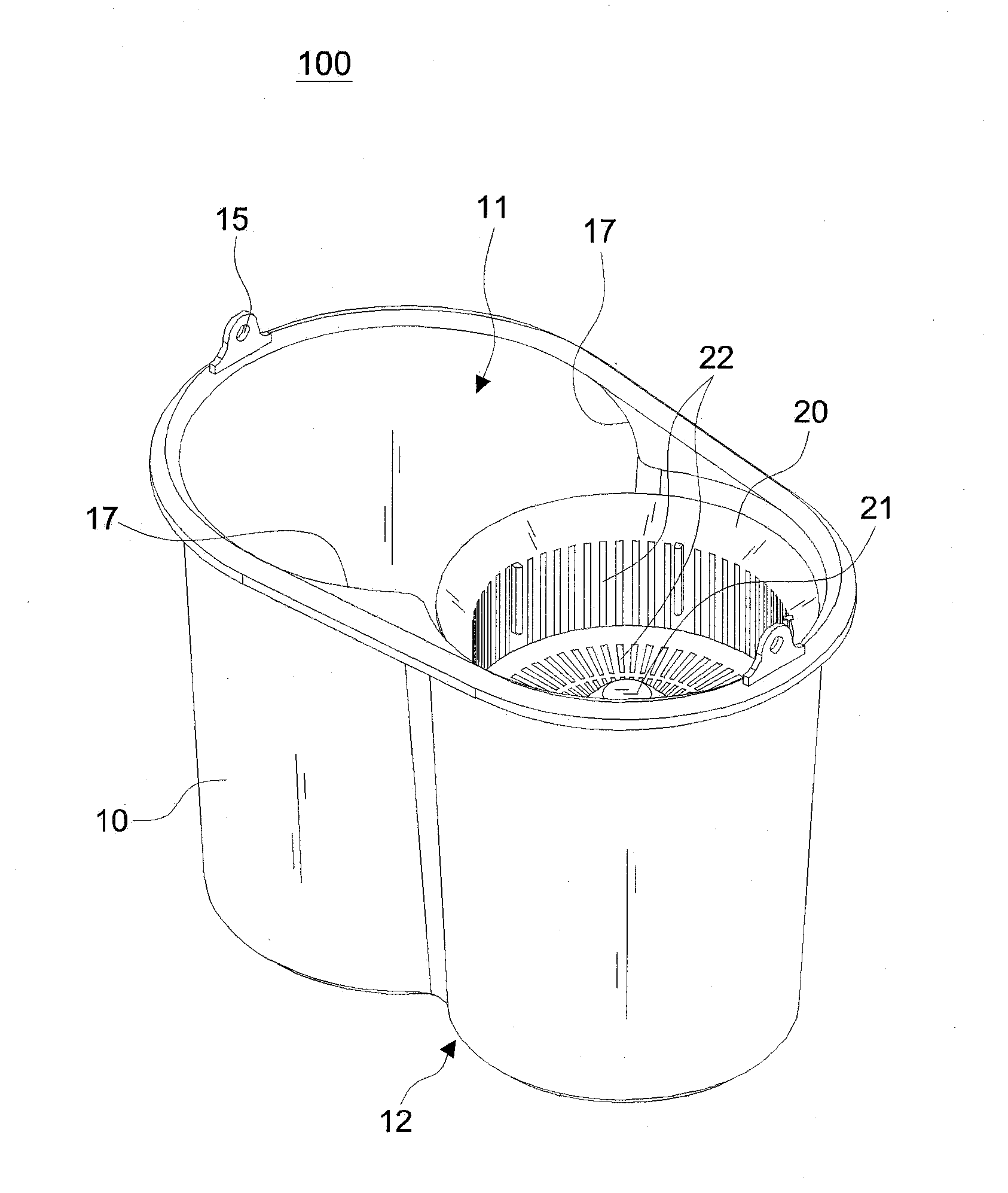
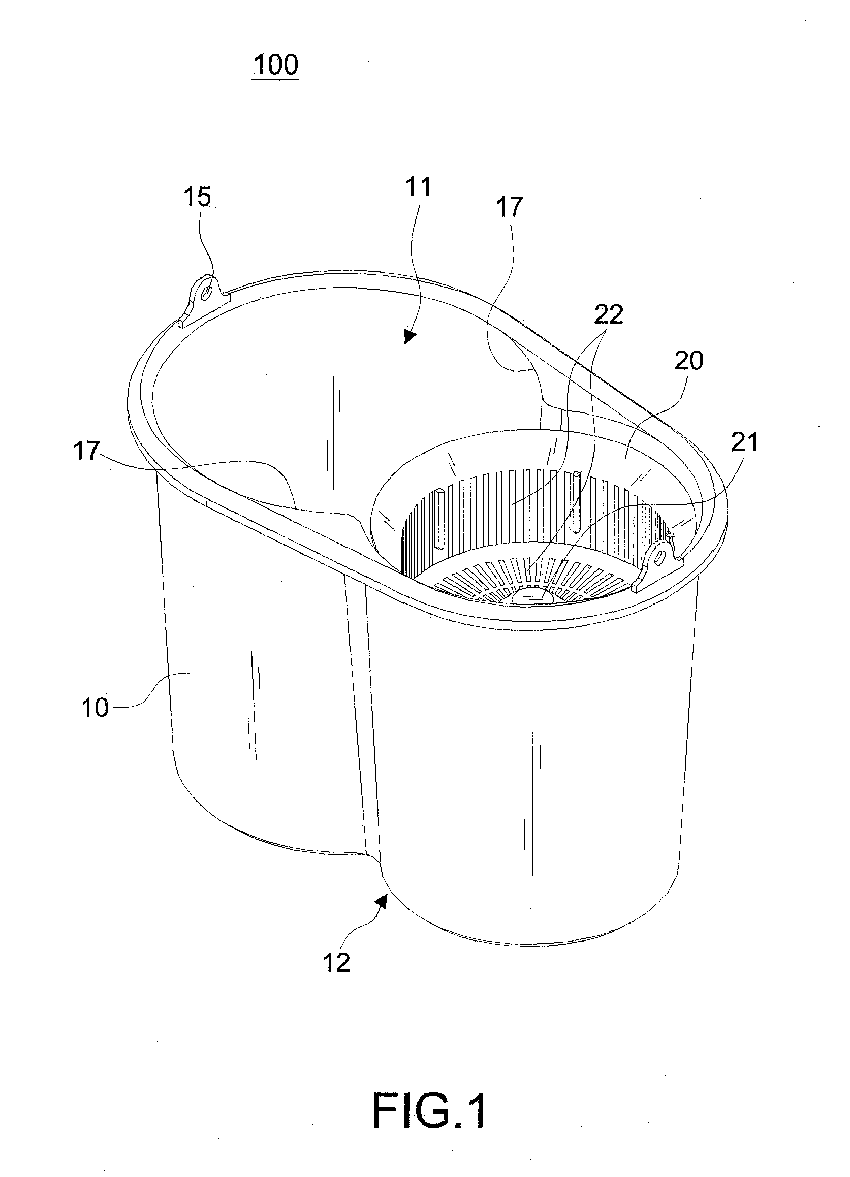
[0020]The non-stepping wringer bucket of the present invention further comprises a handle for facilitating users to carry the wringer bucket, and the bucket body has an opening substantially in an ∞ shape, and a convex cambered surface protruded from the bottom of the bucket body for enhancing a support force of the bucket body, such that when the rotating element is rotated, the non-stepping wringer bucket will not be shaken.

Problems solved by technology

Moreover, the dewatering basket won't be loosened after an easy DIY-assembly (do-it-yourself).

Method used


Image

  • Free-of-bearing rotational positioning device for a dewatering basket of a non-treading type wringer bucket
  • Free-of-bearing rotational positioning device for a dewatering basket of a non-treading type wringer bucket
  • Free-of-bearing rotational positioning device for a dewatering basket of a non-treading type wringer bucket

Examples


Embodiment Construction

[0033]First of all, referring to FIGS. 1 through 6, a wringer bucket 100 in accordance with the invention includes a bucket body 10, a dewatering basket 20, a shaft holder 30, a support shaft 50, and a positioning element 40. The bucket body 10 includes an opening 11 at the top thereof. A projecting seat 13 is extended from the bottom 12 of the bucket body 10 toward inside. The upright support shaft 50 is supported on the projecting seat 13. The dewatering basket 20 is provided with a plurality of dewatering holes 22 at the periphery and the bottom thereof.

[0034]The height of the projecting seat 13 depends on the actual depth of the bucket. Preferably, the projecting seat 13 should be higher than or equal to the horizontal surface of the required amount of water within the bucket body 10. The support shaft 50 can be engaged into the projecting seat 13 (see FIG. 4A). The top 131 of the projecting seat 13 is flat. As shown in FIG. 10, the bottom 12 of the projecting seat 13 has a -sha...


PUM


Abstract

A free-of-bearing rotational positioning device for a dewatering basket of a non-treading type wringer bucket, comprising: a bucket body having a projecting seat being extended from the bottom of the bucket body toward inside; a support shaft being covered and secured by the projecting seat, the upper portion thereof jutting out of the top of the projecting seat to create a connection part; a positioning element having a conic part at the top thereof, the conic part being tapered upward, a positioning surface being formed at the bottom of the conic part and extended outward from the periphery of the support shaft; and a dewatering basket having a driven seat at the center of the bottom thereof. The bottom of the driven seat includes a shaft holder made of non-metal material. In mounting the dewatering basket, the driven seat fits from top to bottom over the connection part of the support shaft. After the lower sleeve passes through positioning element in a compression manner, the positioning surface of the positioning element is stretched into the engagement groove at the center of the shaft holder when returning to its original shape.

Description

BACKGROUND OF THE INVENTION[0001]1. Field of the Invention[0002]The invention relates to a wringer bucket, and more particularly to a wringer bucket that ensures the safety in use since the treading action is not necessary for the operation thereof. Moreover, the dewatering basket does not require a bearing and won't be loosened after a DIY-assembly (do-it-yourself).[0003]2. Description of the Related Art[0004]Mop is one of the cleaning tools used for cleaning a floor, and traditional wringer buckets are used for removing extra water from the mop, and the traditional wringer buckets generally squeeze fabrics of the mop to remove water on the mop fabrics. As disclosed in R.O.C. Pat. No. M338634, a wringer bucket includes a casing, an installing portion, and a rotating unit, wherein the rotating unit includes a retaining element, an axle, a transmission unit and a push rod unit, such that interactions between the aforementioned components drive the rotating unit to rotate to dewater t...

Claims


Application Information

Patent Timeline
IPC IPC(8): A47L13/58
CPCA47L13/58
Inventor CHEN, YUNG-HUA
Owner TUO SHEN INT
Learn More