Eureka AIR delivers breakthrough ideas for toughest innovation challenges, trusted by R&D personnel around the world.

Housing for an electronic device and method for making the housing

a technology for electronic devices and housings, applied in the field of housings, can solve the problems of metal parts being prone to be abraded or corroded to diminish metal luster, metal parts are typically exposed on the outer area of the housing, and failure of electrical elements received in the housing

Inactive Publication Date: 2009-01-08
FIH (HONG KONG) LTD +1
View PDF13 Cites 11 Cited by
  • Summary
  • Abstract
  • Description
  • Claims
  • Application Information

AI Technical Summary

Benefits of technology

[0005]Nowadays, metal parts are usually used to create housings for electronic devices to improve decorative appearance of the housings. However, the metal parts are typically exposed on the outer area of the housing. The metal parts are prone to be abraded or corroded to diminish metal luster during use. Furthermore, the metal parts exposed out of the housings are prone to be inducted to carry static electricity, thereby may cause failure in electrical elements received in the housings.

Problems solved by technology

However, the metal parts are typically exposed on the outer area of the housing.
The metal parts are prone to be abraded or corroded to diminish metal luster during use.
Furthermore, the metal parts exposed out of the housings are prone to be inducted to carry static electricity, thereby may cause failure in electrical elements received in the housings.

Method used


Image

  • Housing for an electronic device and method for making the housing
  • Housing for an electronic device and method for making the housing
  • Housing for an electronic device and method for making the housing

Examples


Embodiment Construction

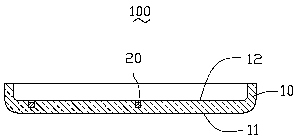
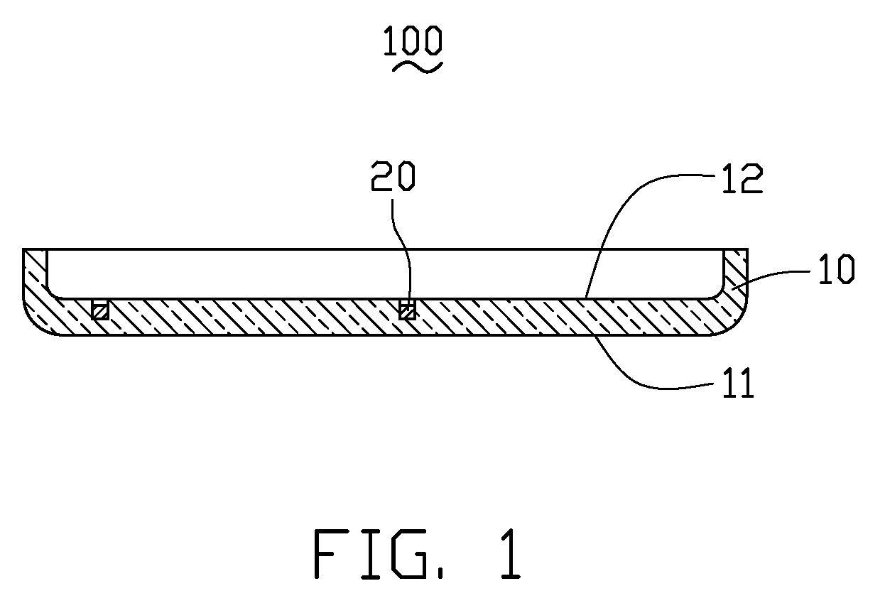
[0016]Referring to FIG. 1, in a present embodiment, a housing 100 includes a transparent substrate 10 and a decorative part 20.

[0017]The substrate 10 includes an outer portion 11 and an inner portion 12 on the opposite side to the outer portion 11. The decorative part 20 is received in the inner portion 12 of the substrate 10. The substrate 10 is made of a transparent moldable material selected from a group consisting of polycarbonate, polymethyl methacrylate, polystyrene, polyvinyl chloride, silicon gel, or any desired combination thereof. The substrate 10 is molded to enclose the decorative part 20 therein via injection molding process. The decorative part 20 is selected from a group consisting of metal, ceramic, plated articles, and glass.

[0018]During use of the housing 100, the decorative part 20 is received in the inner portion 12 of the substrate 10, thereby prevents the decorative part 20 from being abraded or corroded.

[0019]An exemplary method for making the housing 100 is p...


PUM

PropertyMeasurementUnit
Moldableaaaaaaaaaa
Transparencyaaaaaaaaaa
Stress optical coefficientaaaaaaaaaa

Abstract

The housing (100) for an electronic device includes a transparent substrate (10) and a decorative part (20). The transparent substrate is made of a transparent moldable material. The transparent substrate includes an out portion (11) and an inner portion (12). The decorative part is received in the inner portion of the transparent substrate. The substrate is injection molded to enclose the decorative part.

Description

CROSS-REFERENCE TO RELATED APPLICATIONS[0001]This application is related to a co-pending U.S. patent application Ser. No. (Attorney Docket No. US14154), entitled “HOUSING FOR AN ELECTRONIC DEVICE, ELECTRONIC DEVICE USING THE HOUSING, AND METHOD FOR MAKING THE HOUSING”, by Che-Yuan Hsu et al. This application is also related to another co-pending U.S. patent application Ser. No. (Attorney Docket Nos. US14159), entitled “HOUSING FOR ELECTRONIC DEVICES, ELECTRONIC DEVICE USING THE HOUSING AND METHOD FOR MAKING THE HOUSING”, by Che-Yuan Hsu et al. Such applications have the same assignee as the present application and have been concurrently filed herewith. The above-identified applications are incorporated herein by reference. This application claims all benefits accruing under 35 U.S.C. §119 from China Patent Application No. 200710076371.8, filed on Jul. 4, 2007 in the China Intellectual Property Office, the disclosure of which is incorporated herein by reference.BACKGROUND OF THE INVE...

Claims


Application Information

Patent Timeline
IPC IPC(8): B29C45/16H05K7/00
CPCB29C45/14065B29C45/561B29C2045/14122H05K5/0243B29K2705/00B29K2709/08H05K5/02B29C2045/14131
Inventor HSU, CHE-YUANSALMIO, RISTO-PEKKASU, CHENG-WENHUANG, GANGWANG, YAN-MIN
Owner FIH (HONG KONG) LTD
Why Eureka
Eureka Blog
Learn More