LED direct-plugging type multi-chip high power light source

Inactive Publication Date: 2009-01-08
SHENZHEN HOYOL OPTO ELECTRONICS
View PDF9 Cites 4 Cited by
  • Summary
  • Abstract
  • Description
  • Claims
  • Application Information

AI Technical Summary

Benefits of technology

[0007]The present invention provides a LED direct-plugging type multi-chip high power light source with good heat dissipating capability, to solve

Problems solved by technology

As a semiconductor device, LED has the inherent disadvantage of not enduring heat.
The structure comprises disadvantages that sectional area of the heat conducting pole 02 is small, the heat conducting path is long, and the thermal resistance is g

Method used


Image

  • LED direct-plugging type multi-chip high power light source
  • LED direct-plugging type multi-chip high power light source
  • LED direct-plugging type multi-chip high power light source

Examples


Example

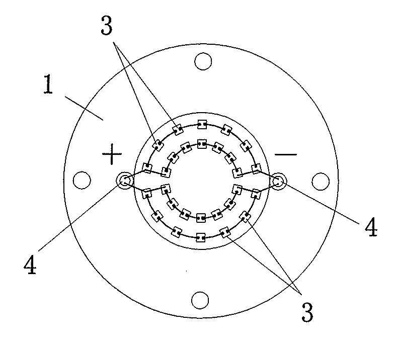
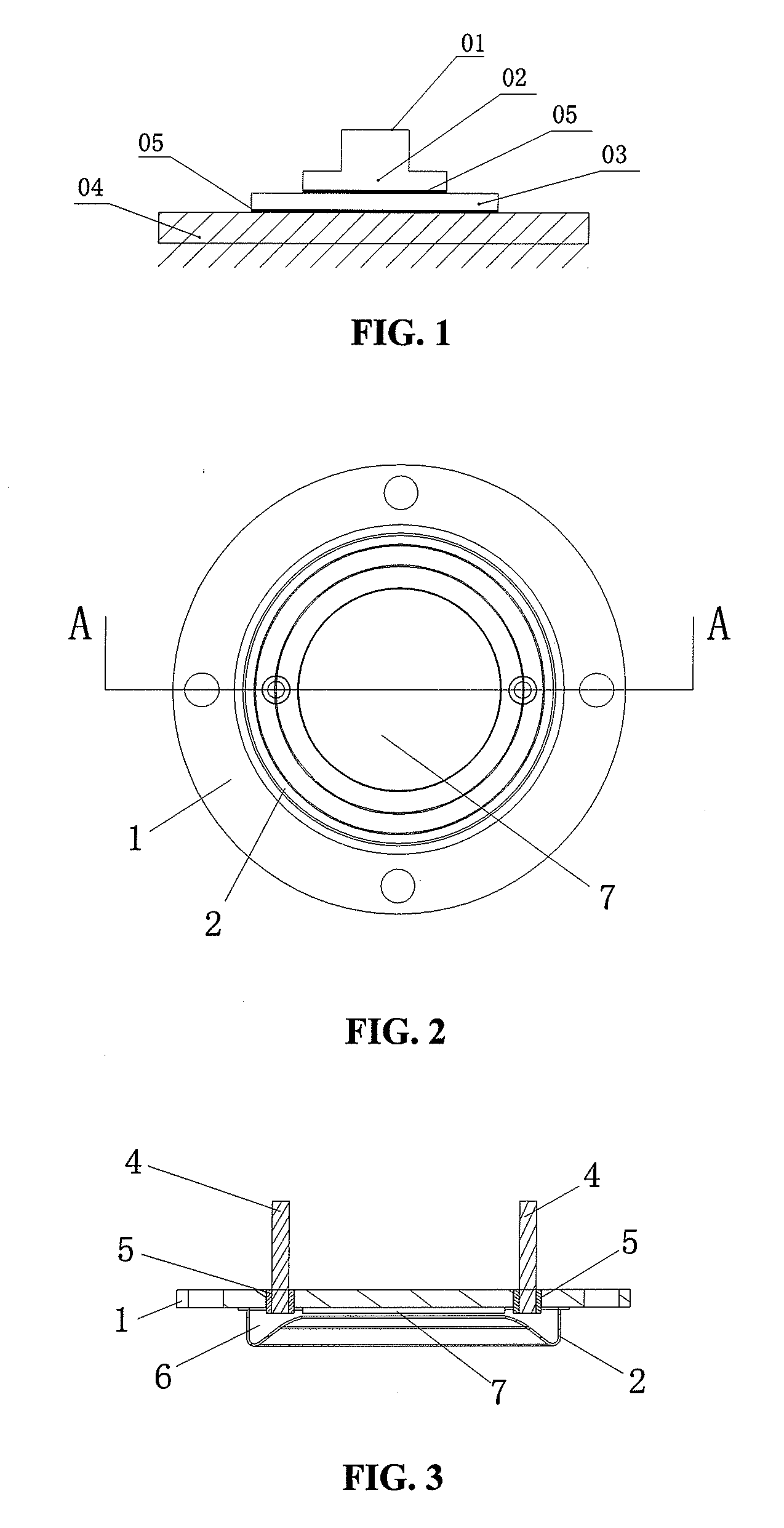
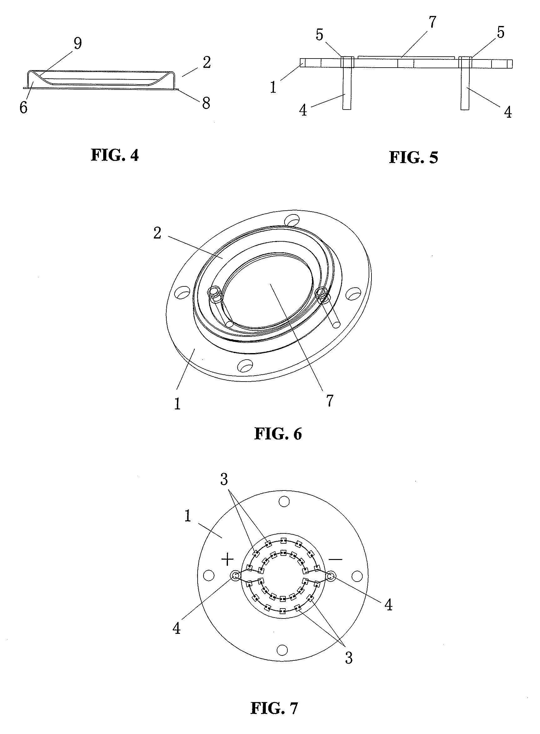
[0023]As illustrated in FIG. 2, FIG. 3, and FIG. 6, the basic structure of a preferred embodiment of the present invention is showed. The said LED direct-plugging type multi-chip high power light source comprises, a heat dissipating substrate 1, a protecting rubber ring 2 mounted at the obverse of the said heat dissipating substrate 1, LEDs 3 mounted on the heat dissipating substrate 1 and in the protecting rubber ring 2, the heat dissipating substrate 1 being provided with two through holes impenetrating its obverse and inverse, in each of the two through holes separately provided with a pin 4 connecting to the LEDs 3, one end of the pin 4 inserted into the through hole and the other end of the pin 4 led out from the inverse of the heat dissipating substrate 1 to outside of the heat dissipating substrate, the part of the pin 4 inserted in the through holes being separated from the heat dissipating substrate 1 by a dielectric 5.

[0024]As illustrated in FIG. 5, in the present embodime...


PUM


Abstract

The present invention provides a LED direct-plugging type multi-chip high power light source, comprising a heat dissipating substrate, a protecting rubber ring mounted at the obverse of the heat dissipating substrate, LEDs fixed on the heat dissipating substrate and in the protecting rubber ring, the heat dissipating substrate being provided with two through holes impenetrating its obverse and inverse, in each of the two through holes separately provided with a pin connecting to the LEDs, one end of the pin inserted into the through hole and the other end of the pin led out from the inverse of the heat dissipating substrate to the outside of the heat dissipating substrate, and the part of the pins inserted in the through holes being separated from the heat dissipating substrate by a dielectric. The heat dissipating substrate is made of high heat conduction metal. In the present invention, the heat dissipating substrate is made of high heat conduction metal, and the heat conducting pole is abolished. Comparing with the conventional art, the present invention decreases the heat dissipating path, increases the sectional area, and eliminates the intermediate link of high thermal resistance. The present invention increases the power of a single light source, decreases the attenuation of light greatly, and increases the useful life greatly.

Description

RELATED APPLICATIONS[0001]The present application is based on, and claims priority from, China Application Number 200720121161.1, filed Jul. 2, 2007, the disclosure of which is hereby incorporated by reference herein in its entirety.BACKGROUND OF THE INVENTION[0002]1. Field of the Invention[0003]The present invention relates to an illuminating device, particularly relates to a high power LED light source.[0004]2. Description of the Related Art[0005]As a new type of light source, LED gradually concerns all the countries in the world. Comparing with the traditional light source, LED involves the advantages: 1, having better safety, belonging to cold light source device, being driven in low voltage, having firm structure, not falling to pieces; having long useful life, lasting 50-100 thousand hours in a good heat dissipation condition, which is much longer than other light sources; 2, having rich colors, being regulated and controlled easily; 3, improving luminous efficiency greatly ye...

Claims


Application Information

Patent Timeline
IPC IPC(8): F21V29/00
CPCF21K9/00F21V29/20F21Y2101/02F21Y2115/10F21V29/89F21V29/70
Inventor CHANG, BAOYANYANG, XIANGHONGXU, ZHENG
Owner SHENZHEN HOYOL OPTO ELECTRONICS
Why Eureka
Try Eureka