
Power module

Active Publication Date: 2021-02-25
NIKO SEMICON
View PDF0 Cites 0 Cited by
  • Summary
  • Abstract
  • Description
  • Claims
  • Application Information

AI Technical Summary

Benefits of technology

The power module and carrier assembly in this disclosure have two main technical features: "the extending portion of the circuit board between the first and second conductive parts" and "the lead frame's upper surface being flush with the extending portion's top surface." These features make the power module capable of handling high voltage or current and have good heat dissipation capabilities.

Problems solved by technology

However, in some circuits, such as a voltage converter circuit, since the power module may be required to operate under a high voltage or high current condition, the power module would generate much heat during the operation thereof.

Method used


Image

  • Power module
  • Power module
  • Power module

Examples


first embodiment

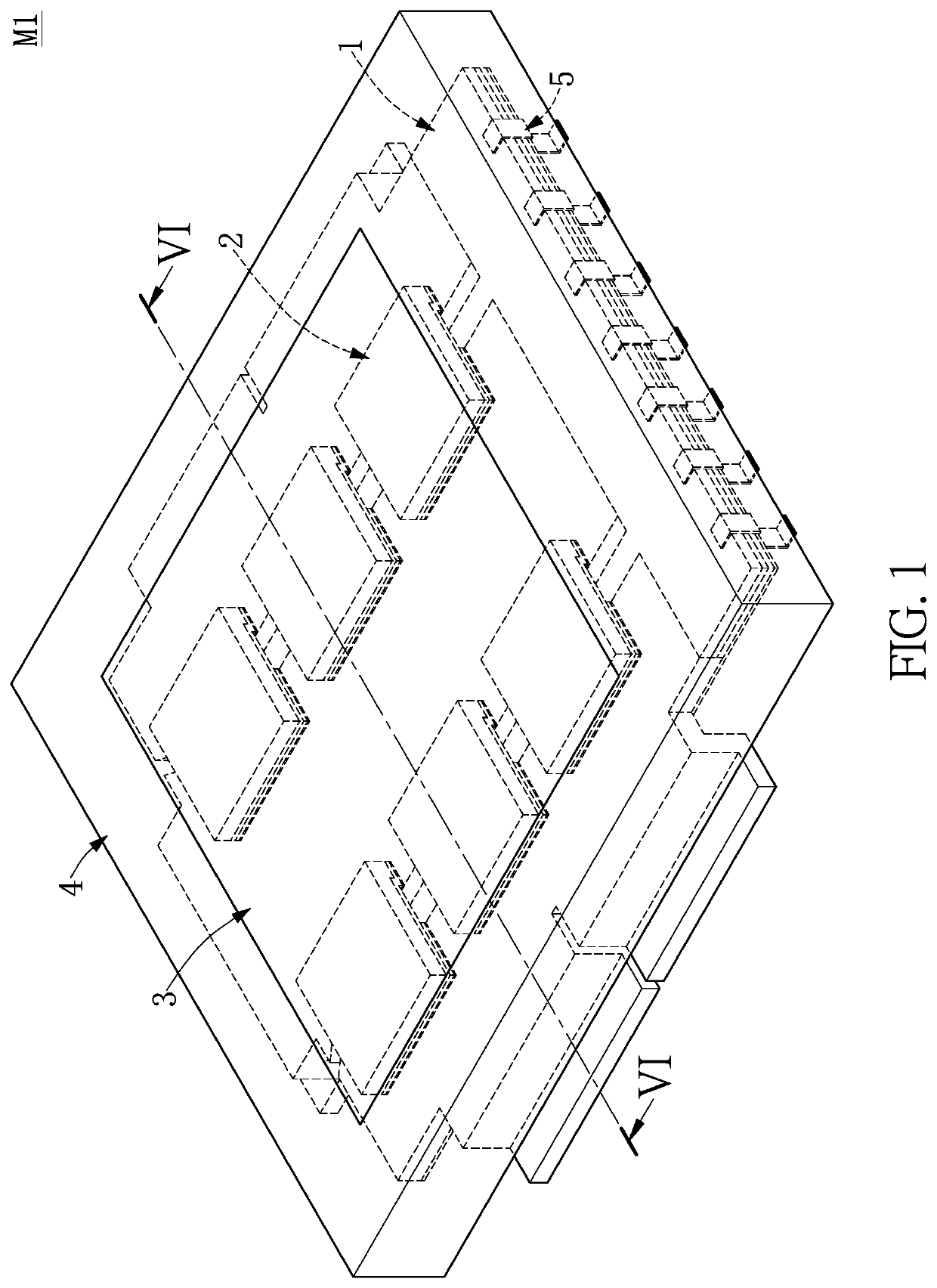
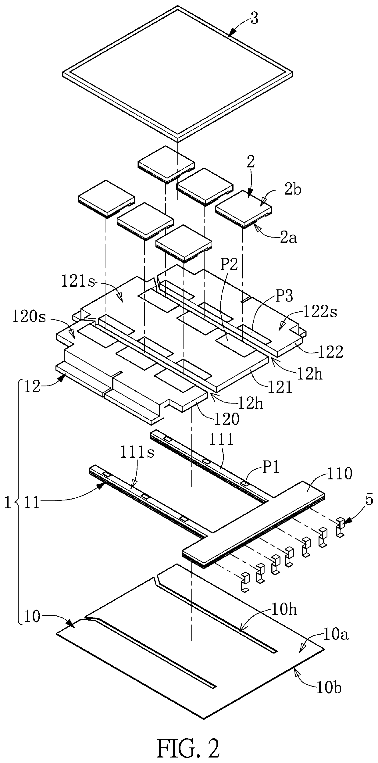
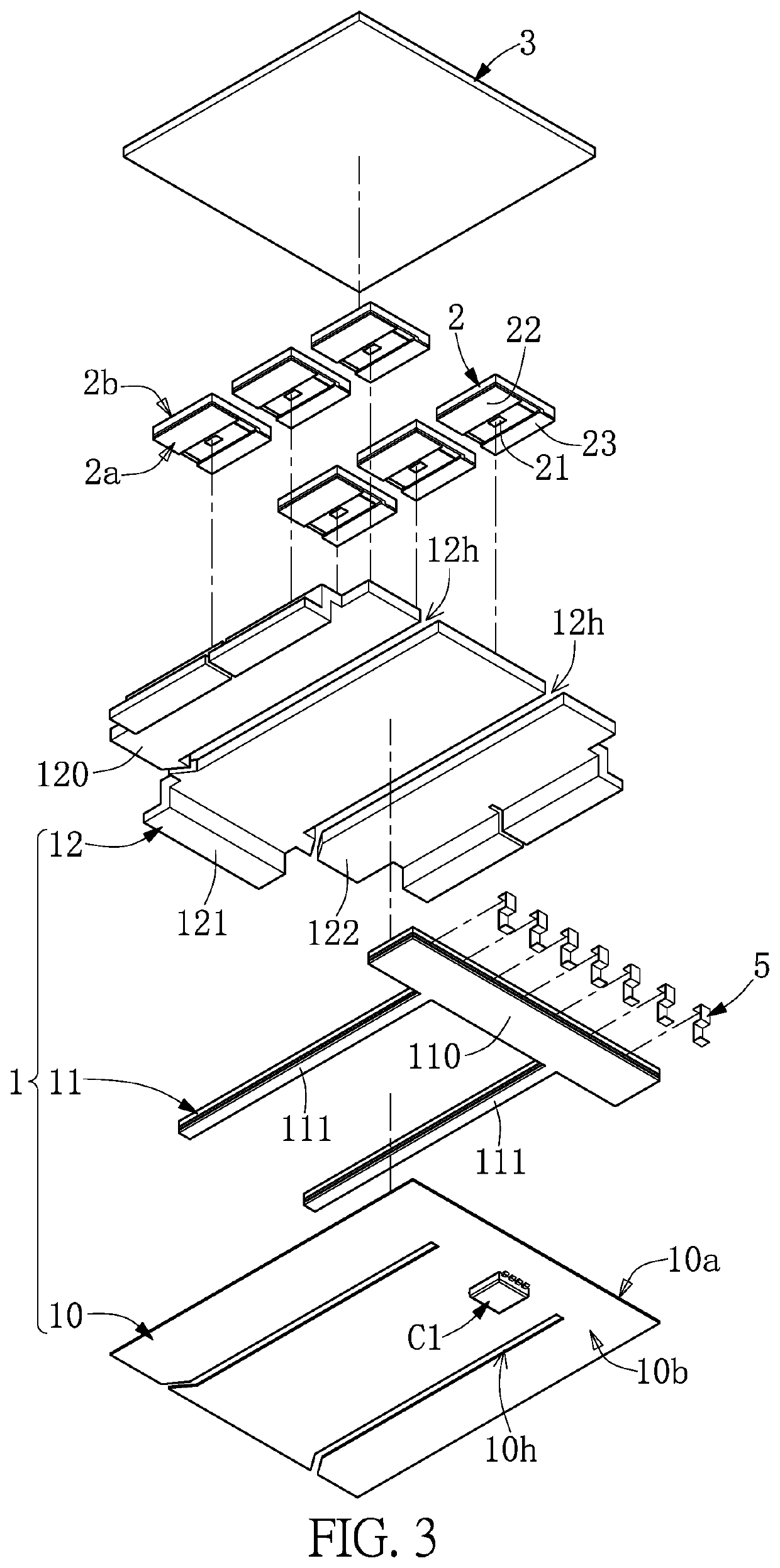
[0022]Reference is made to FIG. 1 to FIG. 4. FIG. 1 is a perspective schematic view of the power module according to a first embodiment of the present disclosure. FIG. 2 is an exploded view of the power module according to the first embodiment of the present disclosure. FIG. 3 is an exploded view of the power module from another viewpoint according to the first embodiment of the present disclosure. FIG. 4 is a perspective schematic view of the power module in which a thermal dissipation plate and a molding layer are omitted according to the first embodiment of the present disclosure.

[0023]As shown in FIG. 1, the power module M1 includes a carrier assembly 1, at least one power device 2 (more than one power device is exemplified in FIG. 1), a thermal dissipation plate 3, a plurality of input / output pins 5, and a molding layer 4.

[0024]In the instant embodiment, the power devices 2 are disposed on the carrier assembly 1. The power devices 2 can be insulated gate bipolar transistors (IG...


PUM


Abstract

A power module including a carrier assembly and a power device disposed on the carrier assembly is provided. The carrier assembly includes a bottom board, a circuit board, a lead frame, and a pad group. The circuit board is disposed on the bottom board and includes a device mounting portion and an extending portion protruding from a side of the device mounting portion. The lead frame disposed on the bottom board includes a first conductive portion and a second conductive portion insulated from each other. The extending portion of the circuit board is disposed between the first and second conductive portions, and an upper surface of the lead frame is flush with a top surface of the extending portion. A pad group includes a first pad disposed on the extending portion, a second pad and a third pad respectively disposed on the first and second conductive portions.

Description

CROSS-REFERENCE TO RELATED PATENT APPLICATION[0001]This application claims the benefit of priority to Taiwan Patent Application No. 108129493, filed on Aug. 19, 2019. The entire content of the above identified application is incorporated herein by reference.[0002]Some references, which may include patents, patent applications and various publications, may be cited and discussed in the description of this disclosure. The citation and / or discussion of such references is provided merely to clarify the description of the present disclosure and is not an admission that any such reference is “prior art” to the disclosure described herein. All references cited and discussed in this specification are incorporated herein by reference in their entireties and to the same extent as if each reference was individually incorporated by reference.FIELD OF THE DISCLOSURE[0003]The present disclosure relates to a power module, and more particularly to a power module for high power operation.BACKGROUND ...

Claims


Application Information

Patent Timeline
IPC IPC(8): H01L23/498H01L23/495H01L23/538H01L23/36H05K7/20H05K1/11H05K1/18
CPCH01L23/49861H01L23/49541H01L23/5385H05K1/181H05K7/205H05K1/111H01L23/36H01L2224/40139H01L23/13H01L23/49811H01L23/4334H01L23/49531H05K7/209
Inventor LENG, CHUNG-MINGHSIEH, CHIH-CHENG
Owner NIKO SEMICON
Learn More