Heat dissipating device

Inactive Publication Date: 2005-03-03
HON HAI PRECISION IND CO LTD +1
View PDF10 Cites 13 Cited by
  • Summary
  • Abstract
  • Description
  • Claims
  • Application Information

AI Technical Summary

Benefits of technology

[0007] Accordingly, an object of the present invention is to provide a heat dissipating device which provides fluent airflow for good heat dissipation capability.
[0008] Another object of the present invention is to provide a heat dissipating device which has simple structure.

Problems solved by technology

Electronic devices such as central processing units (CPUs) generate a lot of heat during normal operation.
This can deteriorate their operational stability and damage associated electronic devices.
This can seriously affect the heat dissipation capability of the heat dissipation device.
However, this improved heat dissipation device has complex structure.
It is not adapted to mass manufacture.

Method used


Image

  • Heat dissipating device
  • Heat dissipating device
  • Heat dissipating device

Examples


Embodiment Construction

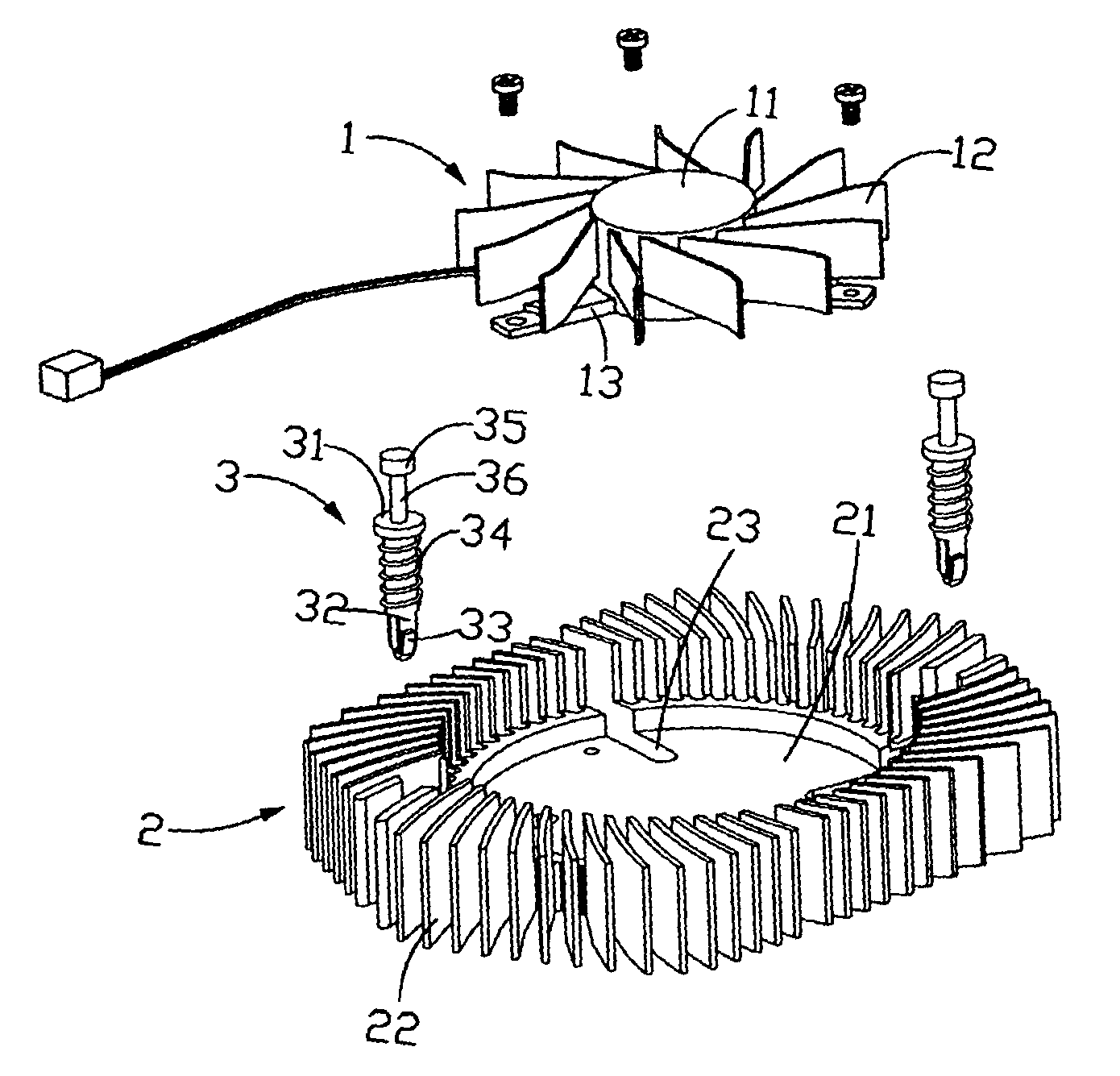
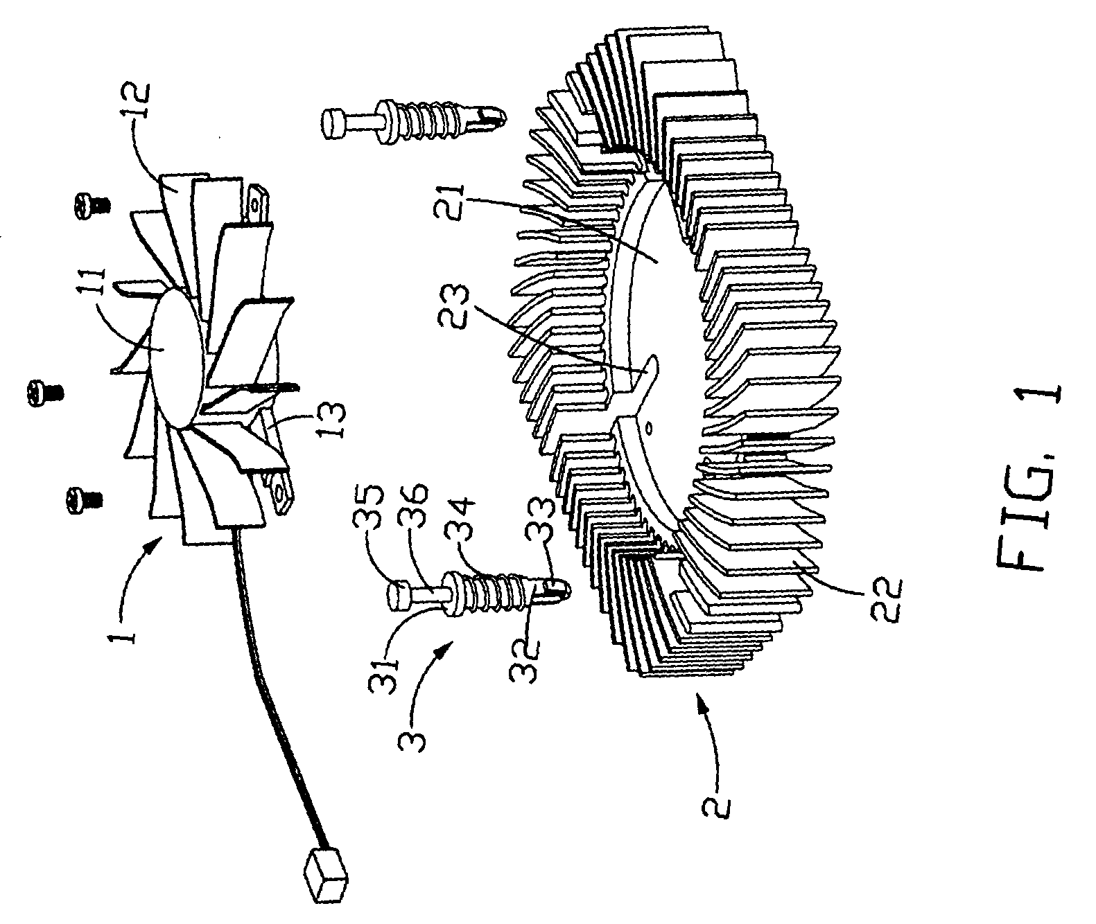
[0016] Referring to FIG. 1, a heat dissipating device in accordance with the preferred embodiment of the present invention comprises a fan 1, a heat sink 2 and a pair of clips 3. The heat dissipating device is adapted for removing heat from an electronic package (not shown) thereunder.

[0017] The fan 1 has an impeller 11 and a plurality of blades 12 radially mounted thereon. The fan 1 has four legs 13 with holes defined thereon, for mounting the fan 1 on the heat sink 2 with screws (not labeled).

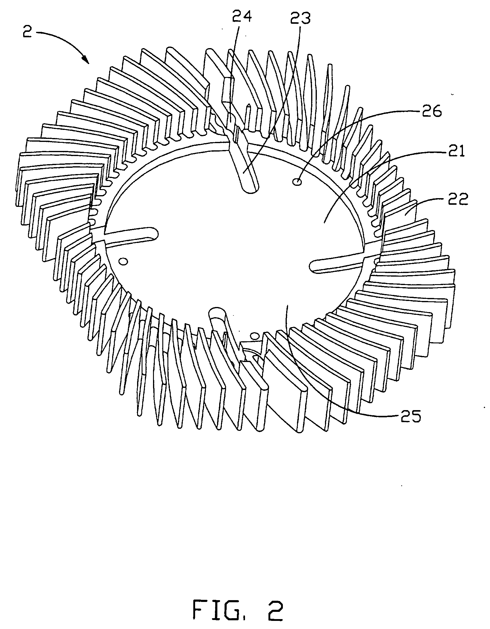
[0018] Referring to FIG. 2, the heat sink 2 includes a circular base 21 and a plurality of curved fins 22 radially and upwardly extending from a periphery of the base 21. The base 21 has an upper surface and a lower surface. The lower surface of the base 21 touches the electronic package (not shown). With the fins 22 surrounding, a chamber is defined therein for receiving the fan 1. Between every two adjacent fins 22, an airflow passage is formed. Four channels 23 are quarterly defined in t...


PUM


Abstract

A heat dissipating device is adapted to remove heat from an electronic package. The heat dissipating device includes a fan (1) for generating airflow and a heat sink (2). The heat sink has a base (21) and a plurality of fins (22). A chamber (25) is defined with the fins surrounding for receiving the fan. At least one channel (23) is defined in the base for allowing airflow directly blowing on the electronic package under the heat sink.

Description

BACKGROUND OF THE INVENTION [0001] 1. Field of the Invention [0002] The present invention relates to a heat dissipating device, and particularly to a heat dissipating device which is attached to an electronic package to remove heat therefrom. [0003] 2. Prior Art [0004] Electronic devices such as central processing units (CPUs) generate a lot of heat during normal operation. This can deteriorate their operational stability and damage associated electronic devices. Thus the heat must be removed quickly to ensure normal operation. [0005]FIG. 4 shows a conventional heat dissipation device 20. The heat dissipation device 20 comprises a flat base 22, a plurality of fins 24 extending from the base 22, and a fan 26 mounted on the fins 24. During operation of the heat dissipation device 20, the fan 26 draws ambient cooling air to the heat dissipation device 20. The air flows down in channels defined between the fins 24 for heat exchange with the fins 24. When the air arrives at the base 22, ...

Claims


Application Information

Patent Timeline
IPC IPC(8): F04D29/58H01L23/373H01L23/467H05K7/20
CPCF04D29/582H01L23/3733H01L23/467H01L2924/0002H01L2924/00
Inventor XU, LI FUYANG, CHIH-HAOHWANG, CHING-BAI
Owner HON HAI PRECISION IND CO LTD
Why Eureka
Try Eureka