Decoding device, decoding method, recording medium, and program

a decoding device and recording medium technology, applied in the direction of color television with bandwidth reduction, signal generators with optical-mechanical scanning, signal systems, etc., can solve the problem that the decoding of 4:2:2 p@hl has not been achieved, the number of component parts has increased, and the decoding speed is fast. to achieve the effect of processing the picture the effect of the speedies

Inactive Publication Date: 2009-01-08
UEDA MAMORU +5
View PDF10 Cites 34 Cited by
  • Summary
  • Abstract
  • Description
  • Claims
  • Application Information

AI Technical Summary

Benefits of technology

[0085]A third decoding device according to the present invention comprises a plurality of slice decoders for decoding a source coded stream for each slice constituting a picture of the source coded stream, and control means for monitoring the decoding statuses of the plurality of slice decoders and controlling the plurality of slice decoders, wherein the control means allocates the slices to the plurality of slice decoders so as to realize the fastest decoding processing of the picture by the slice decoders irrespective of the order of the slices included in the picture.
[0086]A third decoding method according to the present invention comprises a decoding processing control step of controlling the decoding processing of a source coded stream for each slice constituting a picture of the source coded stream by a plurality of slice decoders, and a control step of monitoring the decoding statuses of the plurality of slice decoders and controlling the plurality of slice decoders, wherein in the processing of the control step, the slices are allocated to the plurality of slice decoders so as to realize the fastest decoding processing carried out by the slice decoders irrespective of the order of the slices included in the picture.
[0087]A third program according to the present invention comprises a decoding processing control step of controlling the decoding processing of a source coded stream for each slice constituting a picture of the source coded stream by a plurality of slice decoders, and a control step of monitoring the decoding statuses of the plurality of slice decoders and controlling the plurality of slice decoders, wherein in the processing of the control step, the slices are allocated to the plurality of slice decoders so as to realize the fastest decoding processing carried out by the slice decoders irrespective of the order of the slices included in the picture.
[0088]A fourth decoding device according to the present invention comprises a plurality of slice decoders for decoding a source coded stream for each slice constituting a picture of the source coded stream, and control means for monitoring the decoding statuses of the plurality of slice decoders and controlling the plurality of slice decoders, wherein the control means allocates the slice to be decoded to the slice decoder which ended decoding, of the plurality of slice decoders, irrespective of the order of the slice included in the picture.
[0089]A fourth decoding method according to the present invention comprises a decoding processing control step of controlling the decoding processing of a source coded stream for each slice constituting a picture of the source coded stream by a plurality of slice decoders; and a control step of monitoring the decoding statuses of the plurality of slice decoders and controlling the plurality of slice decoders, wherein in the processing of the control step, the slice is allocated to be decoded to the slice decoder which ended the decoding processing by the processing of the decoding processing control step, of the plurality of slice decoders, irrespective of the order of the slice included in the picture.
[0090]A fourth program according to the present invention comprises a decoding processing control step of controlling the decoding processing of a source coded stream for each slice constituting a picture of the source coded stream by a plurality of slice decoders, and a control step of monitoring the decoding statuses of the plurality of slice decoders and controlling the plurality of slice decoders, wherein in the processing of the control step, the slice is allocated to be decoded to the slice decoder which ended the decoding processing by the processing of the decoding processing control step, of the plurality of slice decoders, irrespective of the order of the slice included in the picture.

Problems solved by technology

Furthermore, the processing by the decoder 15 cannot catch up with the increase in the bit rate and the increase in the number of macroblocks and blocks.
However, in the current MP@ML decoding technique; decoding of 4:2:2 P@HL has not been achieved yet.
Generally, such high-speed signal processing largely increases the circuit scale, leading to the increase in the number of component parts and the increase in power consumption.

Method used


Image

  • Decoding device, decoding method, recording medium, and program
  • Decoding device, decoding method, recording medium, and program
  • Decoding device, decoding method, recording medium, and program

Examples


Embodiment Construction

[0119]A preferred embodiment of the present invention will now be described with reference to the drawings.

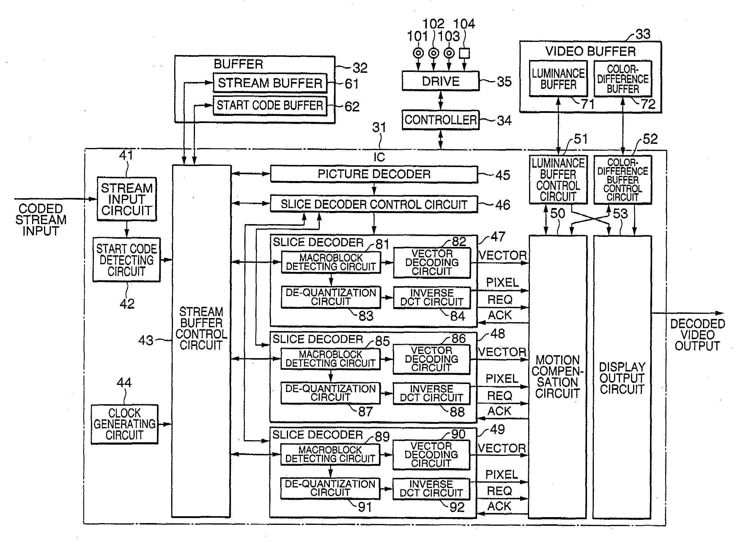
[0120]FIG. 15 is a block diagram showing the circuit structure of an MPEG video decoder according to the present invention.

[0121]The MPEG video decoder of FIG. 15 includes the following constituent elements: an IC 31 constituted by a stream input circuit 41, a start code detecting circuit 42, a stream buffer control circuit 43, a clock generating circuit 44, a picture decoder 45, a slice decoder control circuit 46, slice decoders 47 to 49, a motion compensation circuit 50, a luminance buffer control circuit 51, a color-difference buffer control circuit 52, and a display output circuit 53; a buffer 32 constituted by a stream buffer 61 and a start code buffer 62 and made up of, for example, a DRAM; a video buffer 33 constituted by a luminance buffer 71 and a color-difference buffer 72 and made up of, for example, a DRAM; a controller 34; and a drive 35.

[0122]The stream input circ...


PUM


Abstract

A slice decoder control circuit sequentially supplies the parameter of the picture layer and the write pointer of a first slice to a first slice decoder, the parameter of the picture layer and the write pointer of a second slice to a second slice decoder, and the parameter of the picture layer and the write pointer of a third slice to a third slice decoder, and causes the slice decoders to decode the respective parameters and write pointers. On the basis of the input of signals indicating the completion of decoding processing inputted from the slice decoders, the slice decoder control circuit supplies the write pointer of a fourth slice to the second decoder and causes the second slice decoder to decode the write pointer at timing A, and supplies the write pointer of a fifth slice to the third decoder and causes the third slice decoder to decode the write pointer at timing B. Subsequently, the similar processing is repeated until the last slice is decoded. The operations of a plurality of slice decoders are thus controlled.

Description

TECHNICAL FIELD[0001]This invention relates to a decoding device, a decoding method and a recording medium, and particularly to a decoding device, a decoding method and a recording medium which enable realization of a video decoder conformable to 4:2:2 P@HL capable of carrying out real-time operation on a practical circuit scale.BACKGROUND ART[0002]The MPEG2 (Moving Picture Coding Experts Group / Moving Picture Experts Group 2) video system is a high-efficiency coding system for video signals prescribed by the ISO / IEC (International Standards Organization / International Electrotechnical Commission) 13818-2 and the ITU-T (International Telecommunication Union-Telecommunication sector) recommendations H.262.[0003]A coded stream of MPEG2 is classified by the profile determined in accordance with a coding technique and the level determined by the number of pixels to be handled, and is thus made conformable to a wide variety of applications. For example, MP@ML (Main Profile Main Level) is o...

Claims


Application Information

Patent Timeline
Patent Type & Authority Applications(United States)
IPC IPC(8): H04N7/32H04N7/26H04N21/234H03M7/36H04N5/76H04N5/92H04N7/46H04N7/50H04N11/04H04N19/423H04N19/436H04N19/44H04N19/46H04N19/50H04N19/503H04N19/51H04N19/587H04N19/61H04N19/625H04N19/70H04N19/85
CPCH04N19/00H04N19/70H04N19/577H04N19/436H04N19/61H04N21/234
Inventor UEDA, MAMORUKANESAKA, KOKIOHARA, TAKUMIYAMAMOTO, TAKESHIMIZUNO, KAZUHIROMORITA, TOSHIKAZU
Owner UEDA MAMORU
Why Eureka
Try Eureka