Microplate and methods of using the same

a microplate and micro-plate technology, applied in the field of micro-plates and methods of using the same, can solve the problems of large number of experiments, high cost, and high labor intensity, and achieve the effects of reducing background interference, improving analytical data quality, and reducing labor intensity

Inactive Publication Date: 2009-01-08
APTUIT WEST LAFAYETTE
View PDF25 Cites 25 Cited by
  • Summary
  • Abstract
  • Description
  • Claims
  • Application Information

AI Technical Summary

Benefits of technology

[0012]In accordance with exemplary embodiments of the invention, the inventors have discovered that by using an improved microplate wherein a bottom portion is configured, e.g. comprised of a material with sufficient composition and thickness, to allow the sample to be analyzed in situ by various methods such as, for example, XRPD, Raman, IR, near IR, and/or optical microscopy, with minimized background interference from the bottom portion in the a

Problems solved by technology

This is particularly true in the pre-formulation stage of development because in a drug substance, variations in properties associated with different forms can lead to differences in dissolution rate, oral absorption, bioavailability, levels of gastric irritation, toxicology results, and clinical trial results, for example.
This generally requires that a very large number of experiments be performed.
One disadvantage associated with this method, however, is the amount of time and labor it takes to prepare each sample, i.e. to put the compound of interest, appropriate solvent, and any other desired component of the experiment into individual vials, and then to transfer it to the appropriate holder, label it, and perform the desired analytical technique o

Method used


Image

  • Microplate and methods of using the same
  • Microplate and methods of using the same
  • Microplate and methods of using the same

Examples


Embodiment Construction

[0047]Reference will now be made in greater detail to exemplary embodiments of the invention, examples of which are illustrated in the accompanying drawings. Wherever possible, the same reference numbers will be used throughout the drawings to refer to the same or like parts.

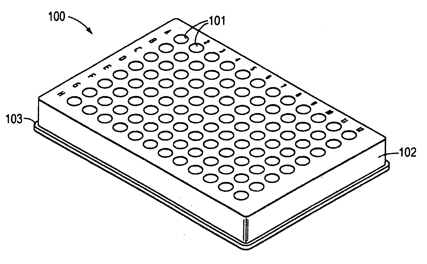
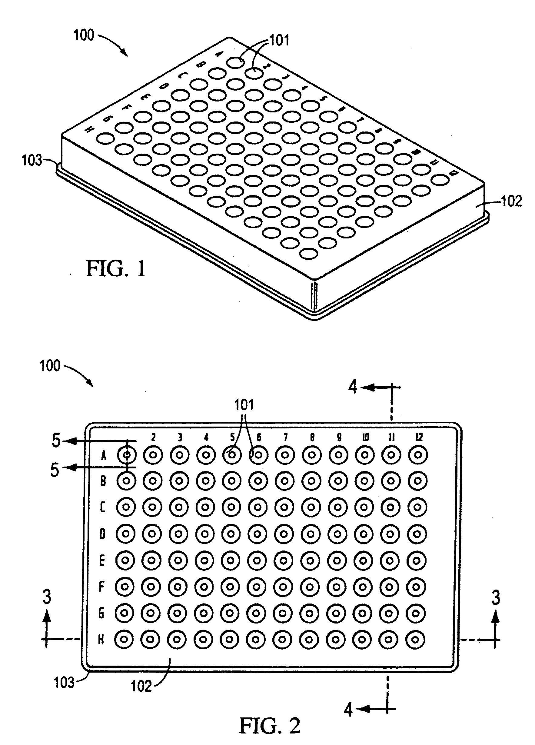
[0048]As seen in FIGS. 1 and 2, an exemplary embodiment of a microplate 100 according to various aspects of the present teachings defines a body 102, a microplate skirt 103, and a plurality of wells 101. The microplate skirt 103 generally is configured to rest against a surface on which the microplate 100 sits, thereby lifting the body 102 and wells 101 slightly above such surface. The microplate skirt 103 may extend substantially around a perimeter (e.g., outer edge) of the microplate 100, as illustrated in FIGS. 1 and 2.

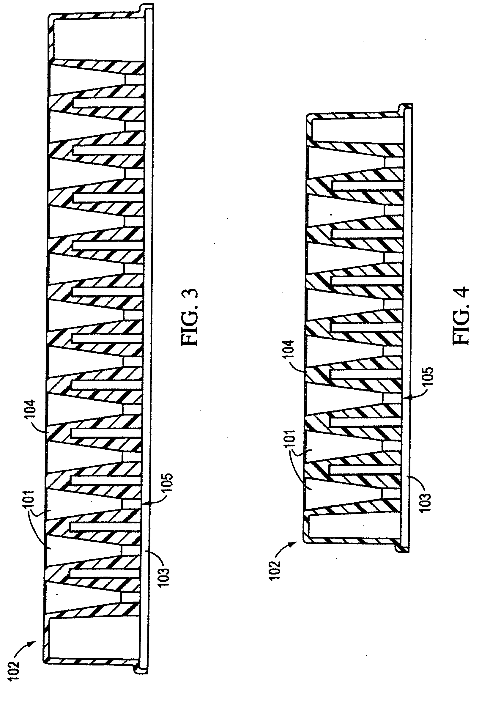
[0049]FIGS. 3 and 4 are cross-sectional views of FIG. 2 taken from 3-3 and 4-4, respectively. The bottom portion 105 can also be seen in FIGS. 3 and 4, and forms the closed end of the wells 101...


PUM


Abstract

Microplates having a body defining a plurality of wells, wherein the wells have at least one bottom portion configured to allow the sample to be analyzed by various methods in situ with minimized background interference in the data obtained, and methods of using the same, are disclosed. The improved microplate may also have wells having certain shapes and/or sizes to allow the sample to be analyzed with minimized background interference in the data obtained. A system for obtaining high-quality XRPD or Raman data is also disclosed.

Description

[0001]This application claims priority to U.S. Provisional Patent Application No. 60 / 942,445, filed Jun. 6, 2007.TECHNICAL FIELD[0002]The invention described herein relates to a method for identifying and characterizing solid forms of a compound by screening and analyzing products using a microplate. The invention also relates to systems and methods for obtaining XRPD and Raman data.BACKGROUND[0003]As is well known, many organic and inorganic compounds can exist in the solid phase as, for example, crystalline, quasi-crystalline, nanocrystalline, and / or amorphous solids. These different solid phases may also exhibit different solid forms. The existence of different solid forms of a compound is important because the physical form of a solid can affect its properties, such as, for example, solubility, water sorption and desorption properties, particle size, hardness, drying characteristics, flow and filterability, compressibility, and density. Different solid forms can have different m...

Claims


Application Information

Patent Timeline
IPC IPC(8): G01N21/01G01N23/20
CPCG01N21/253G01N21/359G01N2021/0346G01N23/20G01N21/65
Inventor STAHLY, BARBARA C.WERNICKI, ALICE
Owner APTUIT WEST LAFAYETTE
Why Eureka
Try Eureka