Image display apparatus and image display system for vehicle

a technology for image display and vehicle, which is applied in the direction of television systems, instruments, transportation and packaging, etc., can solve the problems of vehicle collision, vehicle driver may lose sight of obstacles, and reduce the safety level of driving the vehicl

Active Publication Date: 2009-01-08
DENSO CORP +1
View PDF7 Cites 36 Cited by
  • Summary
  • Abstract
  • Description
  • Claims
  • Application Information

AI Technical Summary

Benefits of technology

[0008]According to an example of the present invention, an image display apparatus is provided as follows. An image capture device is configured to acquire an image of an area including a monitoring target. A display device is configured to display information including an image. A display control device is configured t...

Problems solved by technology

If an obstacle against safe driving is present in the other area within the image captured by the camera, the driver of the vehicle may lose sight of the obstacle.
This may pose a disadv...

Method used


Image

  • Image display apparatus and image display system for vehicle
  • Image display apparatus and image display system for vehicle
  • Image display apparatus and image display system for vehicle

Examples


first embodiment

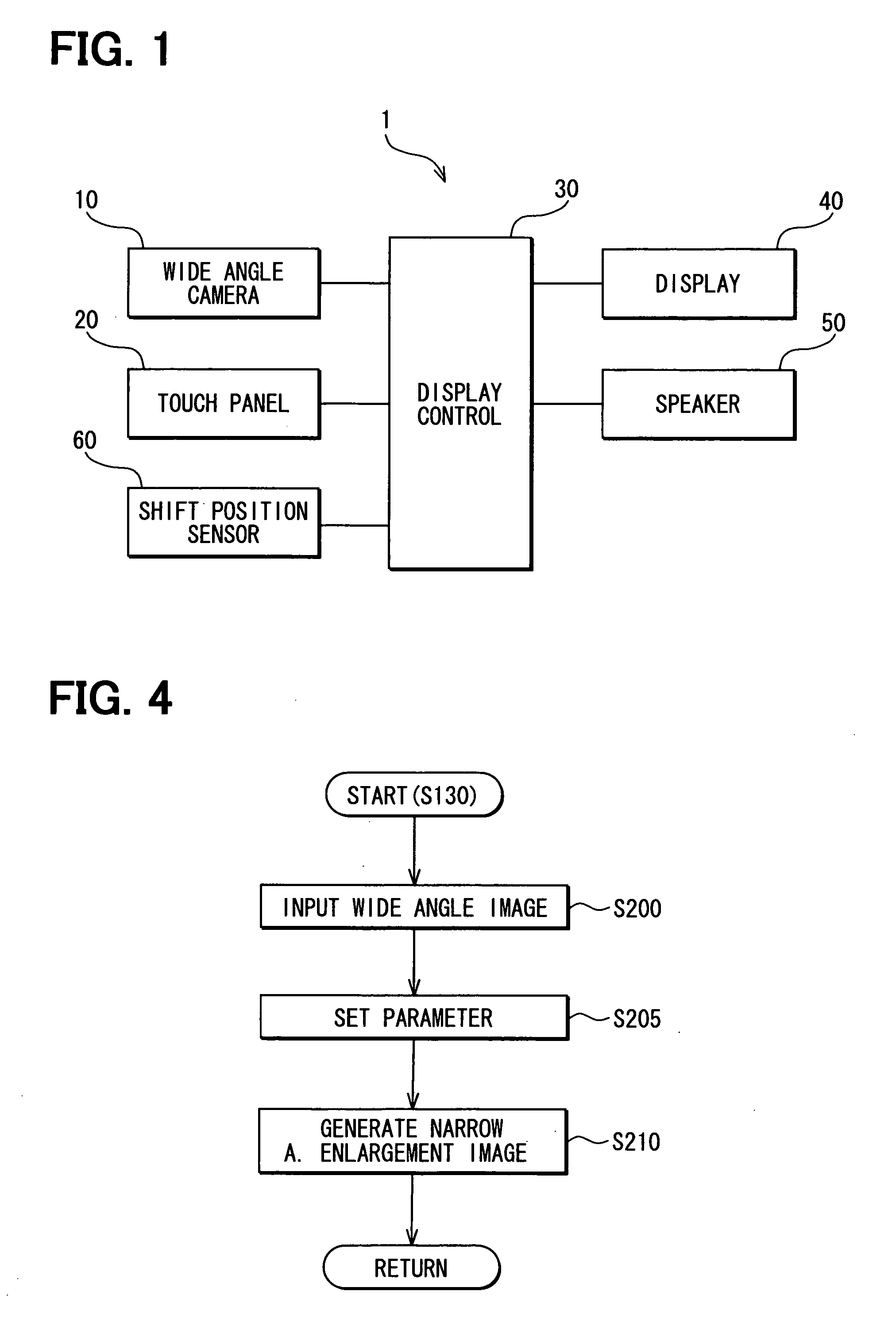
[0021]FIG. 1 is a block diagram illustrating an overall configuration of an in-vehicle image display system 1 according to a first embodiment of the present invention. The in-vehicle image display system 1 is configured to include an image display apparatus and a shift position sensor 60. Further, the image display apparatus is configured to include a wide angle camera 10, a display device 40, a touch panel 20, a speaker 50, and a display controller 30. In other words, the image display apparatus is provided along with the shift position sensor 60 to thereby configure the in-vehicle image display system provided in a subject vehicle.

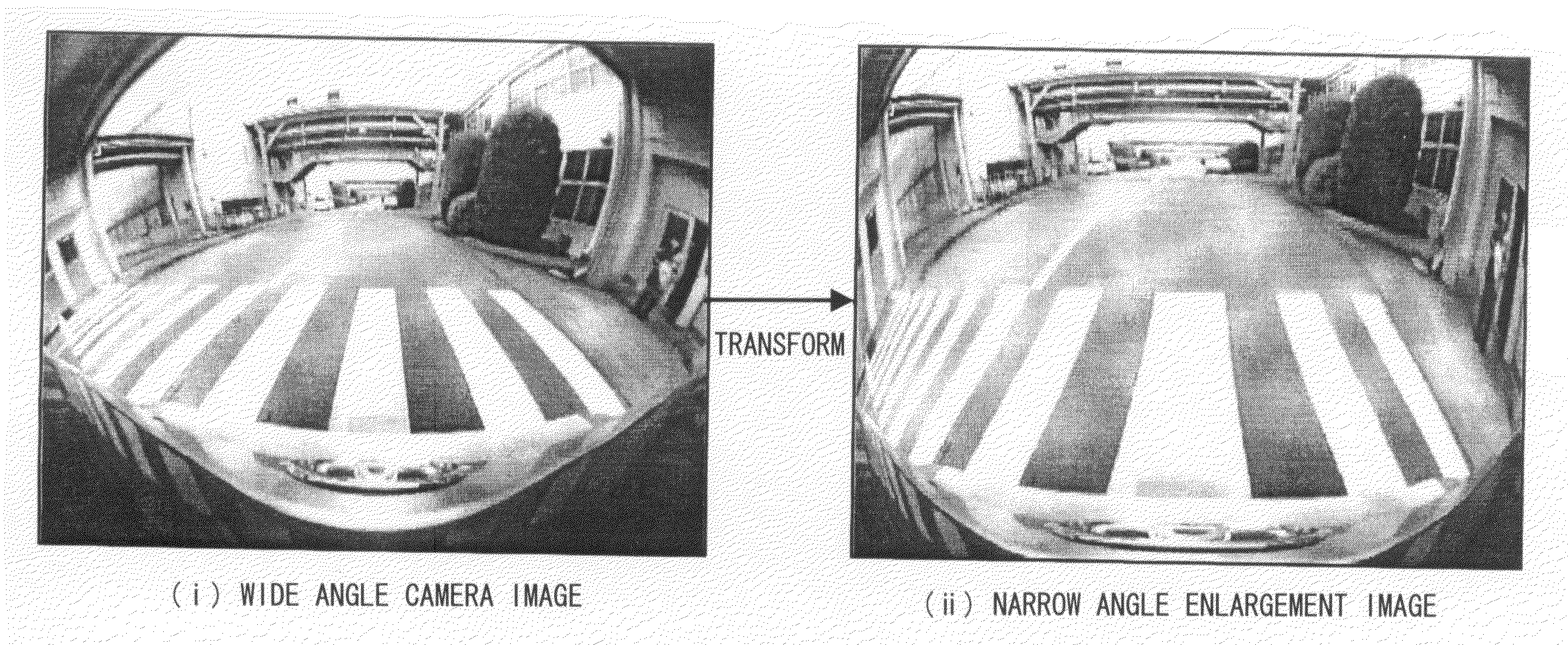
[0022]The wide angle camera 10 is attached to a rear of the vehicle (not shown). The camera 10 functions as an image capture device to have a lens which acquires or capture an image of an area in back of the vehicle as a stereographic projection image or wide angle camera image with a visual angle of 180 degrees. The display device 40 is used for display...

second embodiment

[0080]In the first embodiment, the image transformation is made according to Expressions 1 to 4 and the compressed image is obtained. In a second embodiment, another processing method is adopted to obtain a compressed image in the in-vehicle image display system 1.

[0081]The configuration of the in-vehicle image display system 1 and the display control process by the display controller 30 in the second embodiment are the same as those in the first embodiment. The explanation is therefore mainly made to different part from the first embodiment.

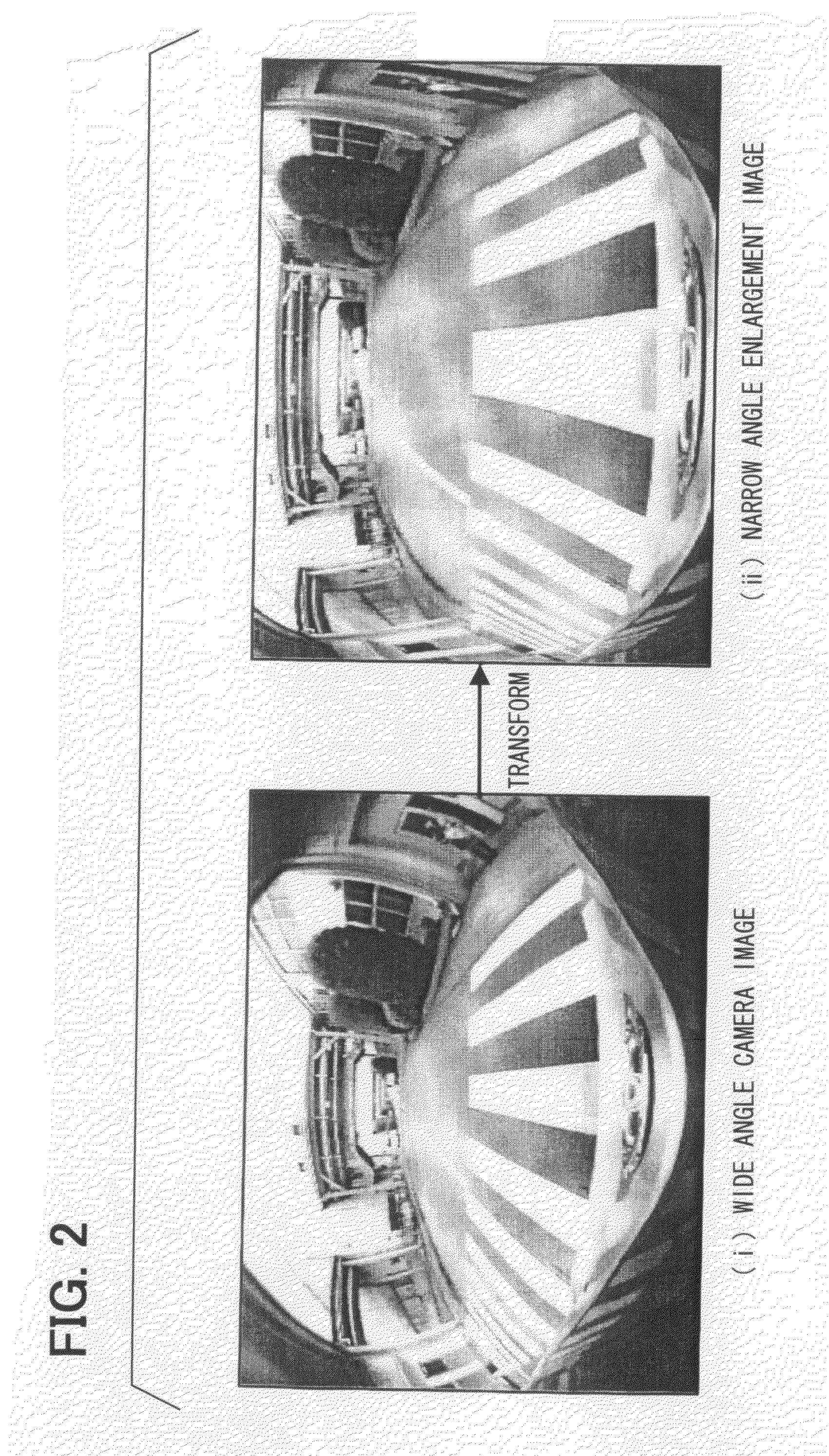
[0082]In the second embodiment, the display controller 30 is configured to transform a stereographic projection image acquired by the wide angle camera 10 into an equal distance projection image to thereby display an enlarged image area and a compressed image area as an integrated single image.

[0083]For instance, in a narrow angle enlargement image generation process of the second embodiment, after the image of the wide angle camera 10 is inputt...


PUM


Abstract

If a display mode is set to a narrow angle enlargement image mode, an enlargement image area is inputted via a touch panel. A transformation is made to compress an image of a not-enlargement image area other than the enlargement image area, and a narrow angle enlargement image is generated to enable simultaneously displaying, as a narrow angle enlargement image, (i) the enlarged image in the enlargement image area and (ii) the compressed image in the not-enlargement image area. When a warning target is detected, a corresponding image area is enlarged. An audio alarm is outputted via a speaker. Further, a new narrow angle enlargement image is generated so as to merge the initial narrow angle enlargement image with an image of enlarging the image area of the warning target. A display window including the new narrow angle enlargement image is then displayed in a display device.

Description

CROSS REFERENCE TO RELATED APPLICATION[0001]This application is based on and incorporates herein by reference Japanese Patent Application No. 2007-174078 filed on Jul. 2, 2007.FIELD OF THE INVENTION[0002]The present invention relates to image display apparatus and an image display system for a vehicle.BACKGROUND OF THE INVENTION[0003]An image display apparatus is configured to enlarge a certain partial area of an image in vicinity to a vehicle captured by a wide angle camera to thereby perform an enlargement image display of the certain partial area if a predetermined condition is satisfied (for example, refer to Patent document 1).[0004]Patent document 1: JP-2005-112267A[0005]In such an enlargement image display of the certain partial area, an image or information in other area other than the certain partial area are invisible in the display. If an obstacle against safe driving is present in the other area within the image captured by the camera, the driver of the vehicle may lose ...

Claims


Application Information

Patent Timeline
IPC IPC(8): G06K9/32
CPCB60R1/00B60R2300/306B60R2300/70H04N5/2628B60R2300/8093H04N5/23238H04N5/23293B60R2300/8033H04N23/634H04N23/698
Inventor AKIBA, KAZUYOSHIHATTORI, TOSHIHIROIMANISHI, MASAYUKI
Owner DENSO CORP
Why Eureka
Try Eureka