
Combustion initiator

Inactive Publication Date: 2009-01-08
BALCH DUANE C +2
View PDF16 Cites 3 Cited by
  • Summary
  • Abstract
  • Description
  • Claims
  • Application Information

AI Technical Summary

Benefits of technology

[0005]With this invention, a combustion initiator is provided which is small and lightweight and which can be easily started, while providing sufficient heat to commence rapid and high temperature combustion of even very wet wood or other fuels. In particular, the invention includes a fuel cell material which is preferably provided within an enclosure comprised of a container and a lid. The fuel cell is formed of a material which may not be particularly easy to cause to commence combustion; but which, once burning, burns at a very high temperature for approximately one and a half minutes, to relatively rapidly both dry wet wood or other difficult to ignite fuels adjacent to the combustion initiator, and cause combustion of such fuels.
[0006]The combustion initiator also includes an ignition pellet adjacent to the fuel cell. This ignition pellet is formed of a material which can be relatively easily caused to commence combustion, provided that the right triggering chemicals are brought into contact with the ignition pellet or other triggering element is activated. The ignition pellet's purpose is to cause the fuel cell material to commence combustion. The ignition pellet is thus relatively small and is oriented adjacent the fuel cell material.

Problems solved by technology

First, the wood fuel must be very dry for a good fire to be started.
Second, even with sufficiently dry wood, the shape and size of the wood is important during the initial fire starting process.
Preparation of such “kindling” can be time consuming and difficult if the proper tools are not available.
Furthermore, the fire is susceptible to being blown out or otherwise failing early in the process if environmental conditions such as high wind or rain are present.

Method used


Image

  • Combustion initiator
  • Combustion initiator
  • Combustion initiator

Examples


Embodiment Construction

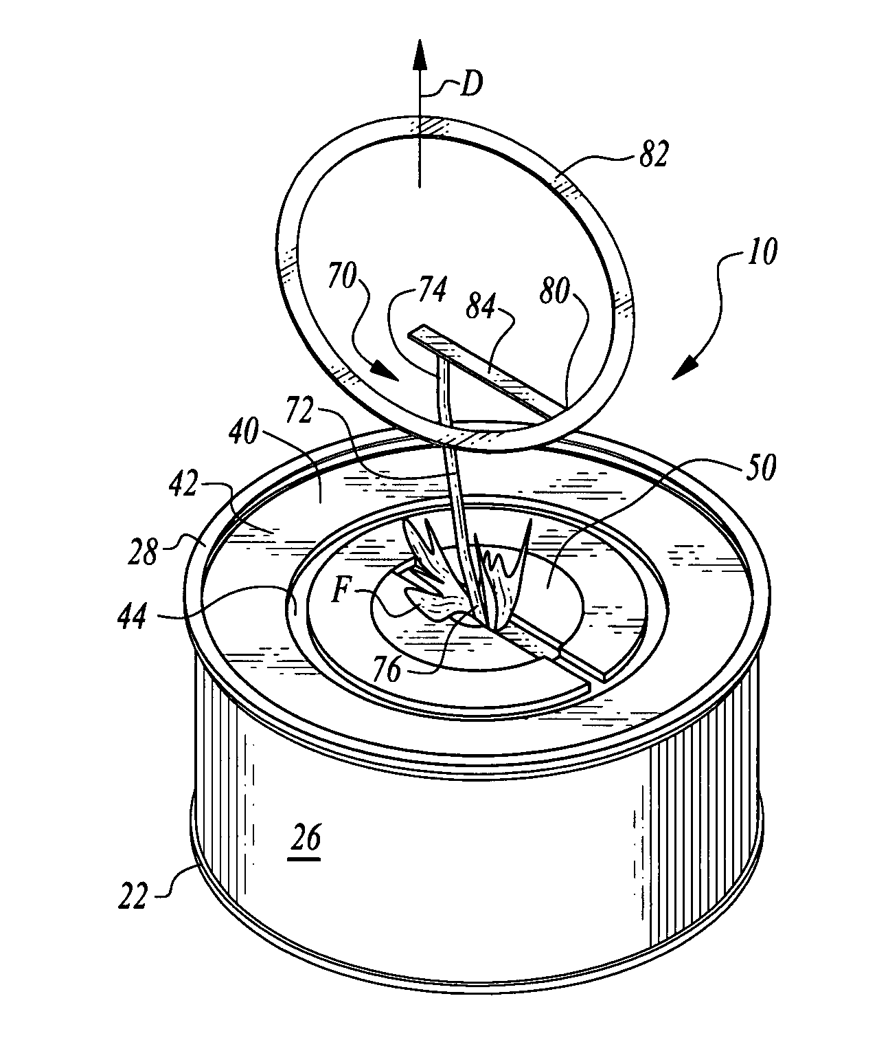
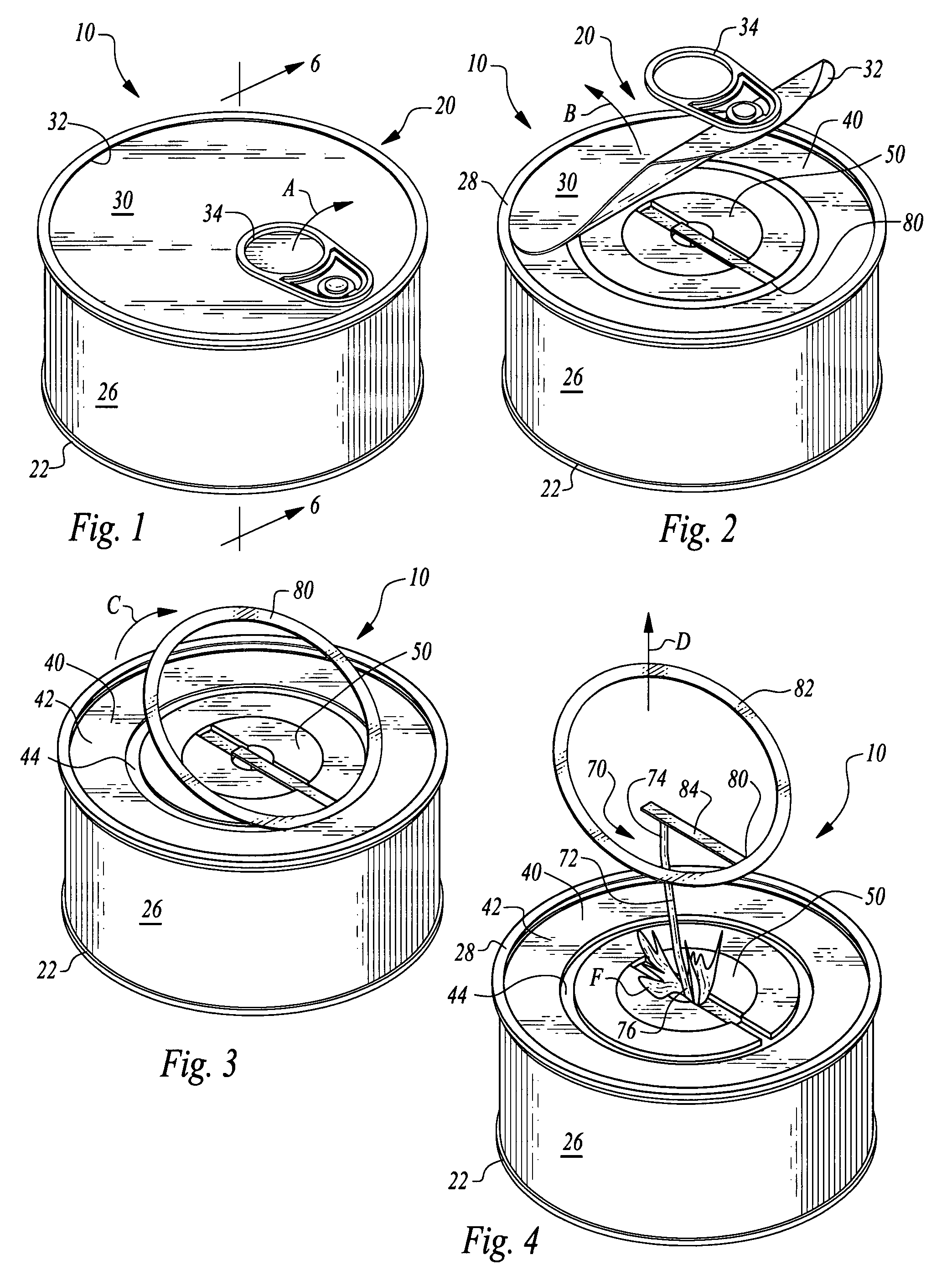
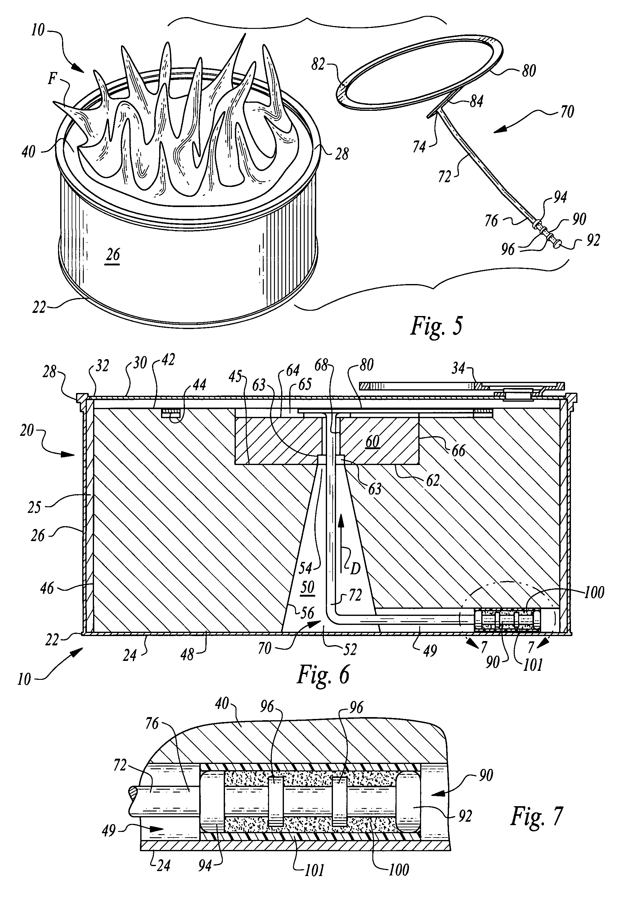
[0031]Referring to the drawings, wherein like reference numerals represent like parts throughout the various drawing figures, reference numeral 10 is directed to a combustion initiator (FIGS. 1-6) according to a preferred embodiment of this invention. The combustion initiator 10 can be utilized to easily initiate combustion of difficult to burn fuels, such as wet wood, placed adjacent to the combustion initiator 10 before activation of the combustion initiator 10. Such activation involves removing a lid 30 from an enclosure 20 containing the combustion initiator 10 and pulling of a pull ring 80 on an igniter train 70 of the combustion initiator 10 until fire F results (FIGS. 4 and 5).

[0032]In essence, and with particular reference to FIGS. 1-6, basic details of the combustion initiator 10 of this invention are described according to the preferred embodiment. The combustion initiator 10 preferably is contained within an enclosure 20 formed of a container 22 and a lid 30 which seals t...


PUM


Abstract

The combustion initiator of this invention preferably includes at least two separate combustible chemical constituents including a fuel cell and an ignition pellet. An igniter has a third combustible material thereon which can be manually caused to move and bring the combustible material into contact with the ignition pellet. The combustible material and ignition pellet are highly reactive with one another so that such contact therebetween causes the ignition pellet to commence combustion. The ignition pellet is adjacent the fuel cell and combusts with sufficient temperature to cause the fuel cell to commence combustion. The fuel cell and ignition pellet are preferably contained within an enclosure which protects the igniter from being manipulated unless the enclosure is first opened. The fuel cell material burns hot enough and long enough to cause combustion of surrounding fuels, such as wood.

Description

CROSS-REFERENCE TO RELATED APPLICATIONS[0001]This application claims benefit under Title 35, United States Code §119(e) of U.S. Provisional Application No. 60 / 830,740 filed on Jul. 12, 2006.FIELD OF THE INVENTION[0002]The following invention relates to devices for initiating combustion of fuels. More particularly, this invention relates to combustion initiators which utilize multiple chemical fuels which exhibit an exothermic combustion reaction of sufficiently long duration and with sufficient heat to initiate combustion of other fuels, such as wood or other cellulosic materials, even when wet. More particularly, this invention relates to combustion initiators which include at least two separate combustible components, a first of which is more easily caused to commence combustion than the other, and a second of which requires a high degree of heat to commence combustion and which combusts over a longer period of time than the first component.BACKGROUND OF THE INVENTION[0003]Most co...

Claims


Application Information

Patent Timeline
IPC IPC(8): F23Q1/02
CPCC10L11/04C10L5/368
Inventor BALCH, DUANE C.LOVEJOY, THOMAS A.NIEMEYER, DENIS R.
Owner BALCH DUANE C
Features
  • Generate Ideas
  • Intellectual Property
  • Life Sciences
  • Materials
  • Tech Scout
  • Unparalleled Data Quality
  • Higher Quality Content
  • 60% Fewer Hallucinations
Learn More