Electrosurgical system

a technology of electrosurgical and surgical equipment, applied in the field of electrosurgical equipment, can solve problems such as still remaining

Inactive Publication Date: 2009-01-08
GYRUS MEDICAL LTD
View PDF12 Cites 241 Cited by
  • Summary
  • Abstract
  • Description
  • Claims
  • Application Information

AI Technical Summary

Benefits of technology

[0015]Thus, when an instrument is active, not only is this shown by the illumination of the illuminated area, but the distal tip of that instrument is illuminated to aid visualisation of the target surgical site.
[0016]The indication means shows the user of the electrosurgical system which of the various electrosurgical assemblies is “active”, and will be energised when the user activates the switch means. This helps to avoid confusion in the operating theatre, as well as the need for the user to refer back to the generator before activating the switch means.

Problems solved by technology

However, even when all of these instruments have been connected, a problem still remains.
Most of these electrosurgical generators only allow for the operation of one of the attached instruments at any one time, and there is a problem for the user in knowing which of the many instruments is currently selected for operation.

Method used


Image

  • Electrosurgical system
  • Electrosurgical system
  • Electrosurgical system

Examples


Embodiment Construction

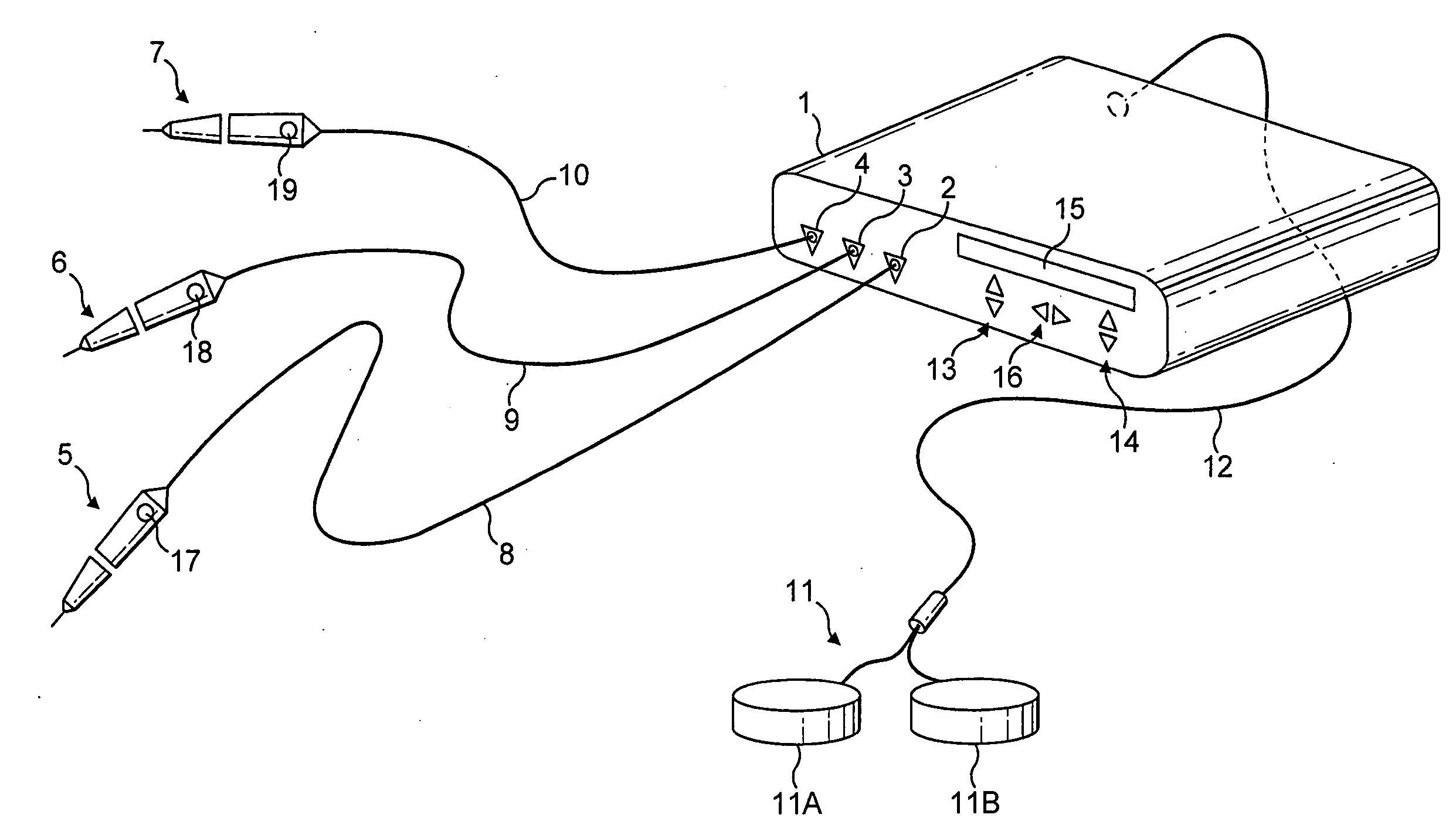
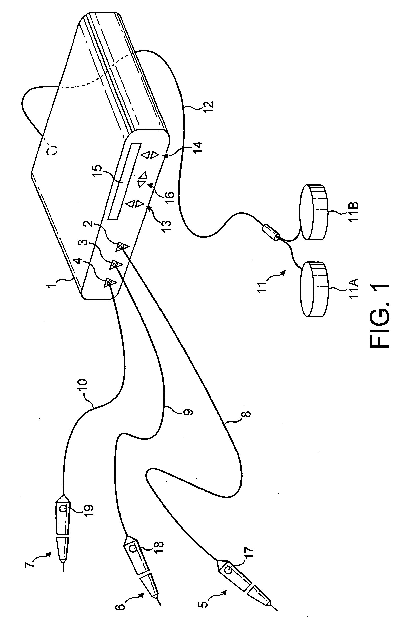
[0030]Referring to FIG. 1, a generator 1 has a output sockets 2, 3, 4, providing a radio frequency (RF) output for electrosurgical instruments 5, 6, 7, via respective connection cords 8, 9, 10. Activation of the generator 1 may be performed from the instruments 5, 6, 7, via handswitches (not shown), or by means of a footswitch unit 11, as shown, connected to the rear of the generator by a footswitch connection cord 12. In the illustrated embodiment, the footswitch unit 11 has two footswitches 11A and 11B for selecting a coagulation mode and a cutting mode of the generator 1 respectively. The generator front panel has push buttons 13 and 14 for respectively setting coagulation and cutting power levels, which are indicated in a display 15. Push buttons 16 are provided as a means for selection between the instruments 5, 6, and 7.

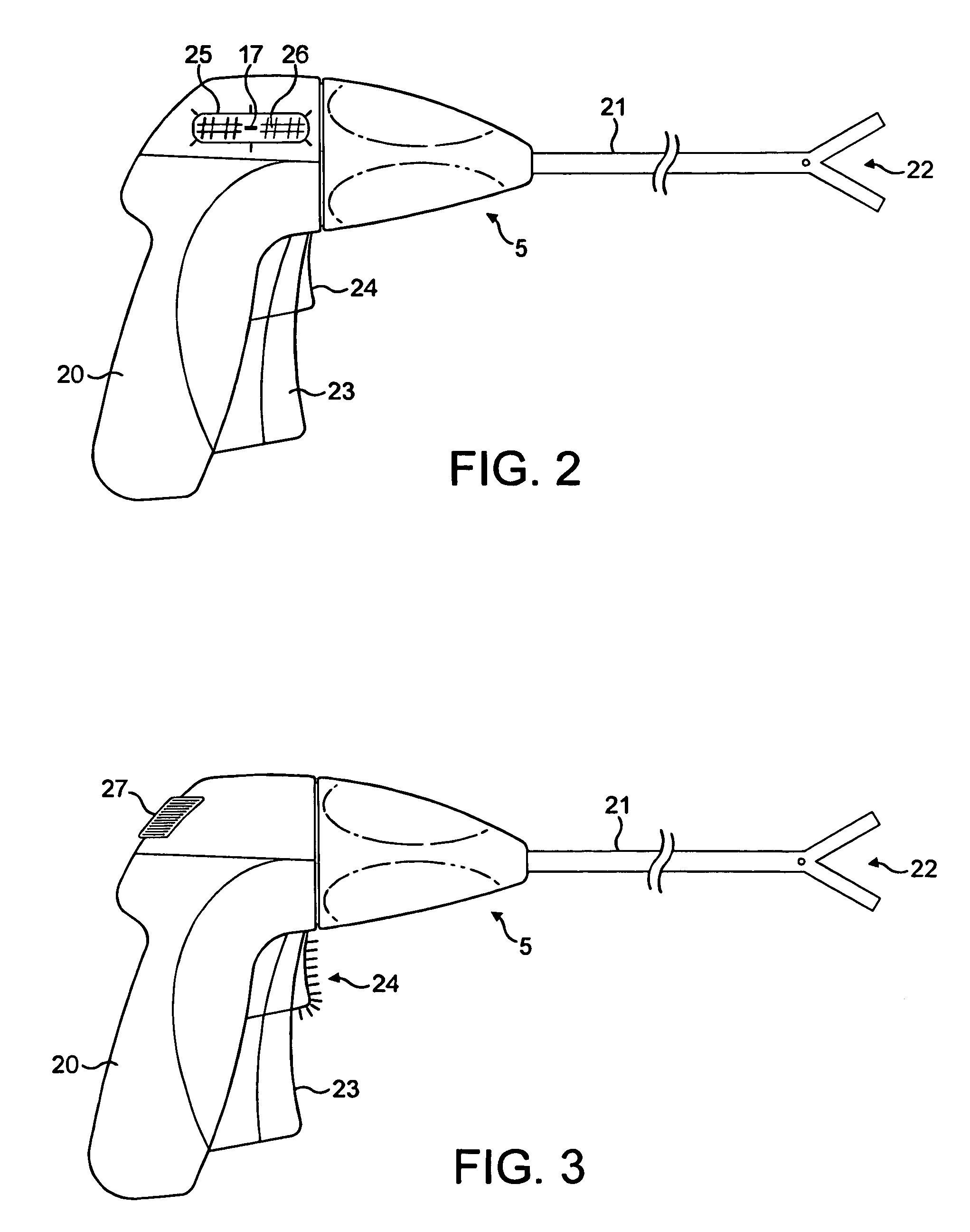
[0031]The instruments 5, 6, 7, have lamps 17, 18, 19, to show the status of the instruments. If, for example, a user of the electrosurgical system wishes to us...


PUM


Abstract

An electrosurgical system includes an electrosurgical generator (1) with a plurality of output connections (2, 3, 4), only one of the output connections at any one time being active in that it is able to receive radio frequency power. A plurality of electrosurgical assemblies, each including an electrosurgical instrument (5, 6, 7) and a cable (8, 9, 10) are connected to the generator (1) via the output connections. The electrosurgical assemblies each include indication means such as lamps (17, 18, 19), illuminating when that particular electrosurgical assembly is connected to the active output connection. A switch means, such as a footswitch (11) or handswitches (24, 27) on the instruments, send a signal to the generator to cause an RF waveform to be provided at the active output connection.

Description

BACKGROUND OF THE INVENTION[0001]This invention relates to an electrosurgical system including an electrosurgical generator, and a plurality of electrosurgical instruments for use therewith.[0002]The majority of electrosurgical generators are designed to have only one instrument attached to the generator at any one time. However, there is an increasing trend, with ever more sophisticated electrosurgery systems, to have multiple instruments connected to the generator at any one time. U.S. Pat. Nos. 5,342,356 and 6,508,809 are two examples of electrosurgical systems in which multiple instruments can be connected to a single generator. These patents describe how shaped connectors, colour coding and distinct symbols can be used to assist with the connection of these multiple instruments, and to ensure that the correct instrument is connected to the appropriate output of the generator.[0003]However, even when all of these instruments have been connected, a problem still remains. Most of ...

Claims


Application Information

Patent Timeline
Patent Type & Authority Applications(United States)
IPC IPC(8): A61B18/04
CPCA61B18/1206A61B18/14A61B2018/1273A61B2018/00178A61B2018/124A61B18/1445
Inventor CURTIS, RICHARD J.NEWTON, MICHAEL DAVID
Owner GYRUS MEDICAL LTD
Why Eureka
Try Eureka