
System and Method for Remote Monitoring and Controlling of Facility Energy Consumption

a technology for energy consumption and facilities, applied in adaptive control, process and machine control, instruments, etc., can solve the problems of increasing the cost and time of obtaining the required information, and the cost and time of controlling the energy consumption systems and components of the facility, so as to increase the integrity of energy consumption data and enhance the acquisition of energy consumption data

Inactive Publication Date: 2009-01-08
TEXAS A&M UNIVERSITY
View PDF18 Cites 56 Cited by
  • Summary
  • Abstract
  • Description
  • Claims
  • Application Information

AI Technical Summary

Benefits of technology

The present invention provides an improved system and method for remotely monitoring and controlling energy consumption of a facility. The system receives energy consumption data and environmental data from the facility and analyzes it to determine if the energy consumption system needs to modify its operating parameters to increase efficiency. The system can then automatically modify the operating parameters and initiate the desired modification remotely from the facility, reducing the need for costly and time-consuming site visits. The invention also enhances energy consumption data integrity by monitoring and modifying the data collection rate and providing enhanced energy consumption data acquisition in response to predetermined events.

Problems solved by technology

Obtaining the required information, however, generally requires access to the facility and / or the energy consumption systems and components.
Accordingly, obtaining the required information is generally expensive and time consuming.
Additionally, controlling the energy consumption systems and components of a facility also generally requires expensive and time-consuming site visits to the facility.
For example, changes in energy consumption efficiency may require changing the operating parameters of an energy consumption component or system, thereby requiring physical inspection, repair or modification to the component or system.

Method used


Image

  • System and Method for Remote Monitoring and Controlling of Facility Energy Consumption
  • System and Method for Remote Monitoring and Controlling of Facility Energy Consumption
  • System and Method for Remote Monitoring and Controlling of Facility Energy Consumption

Examples


Embodiment Construction

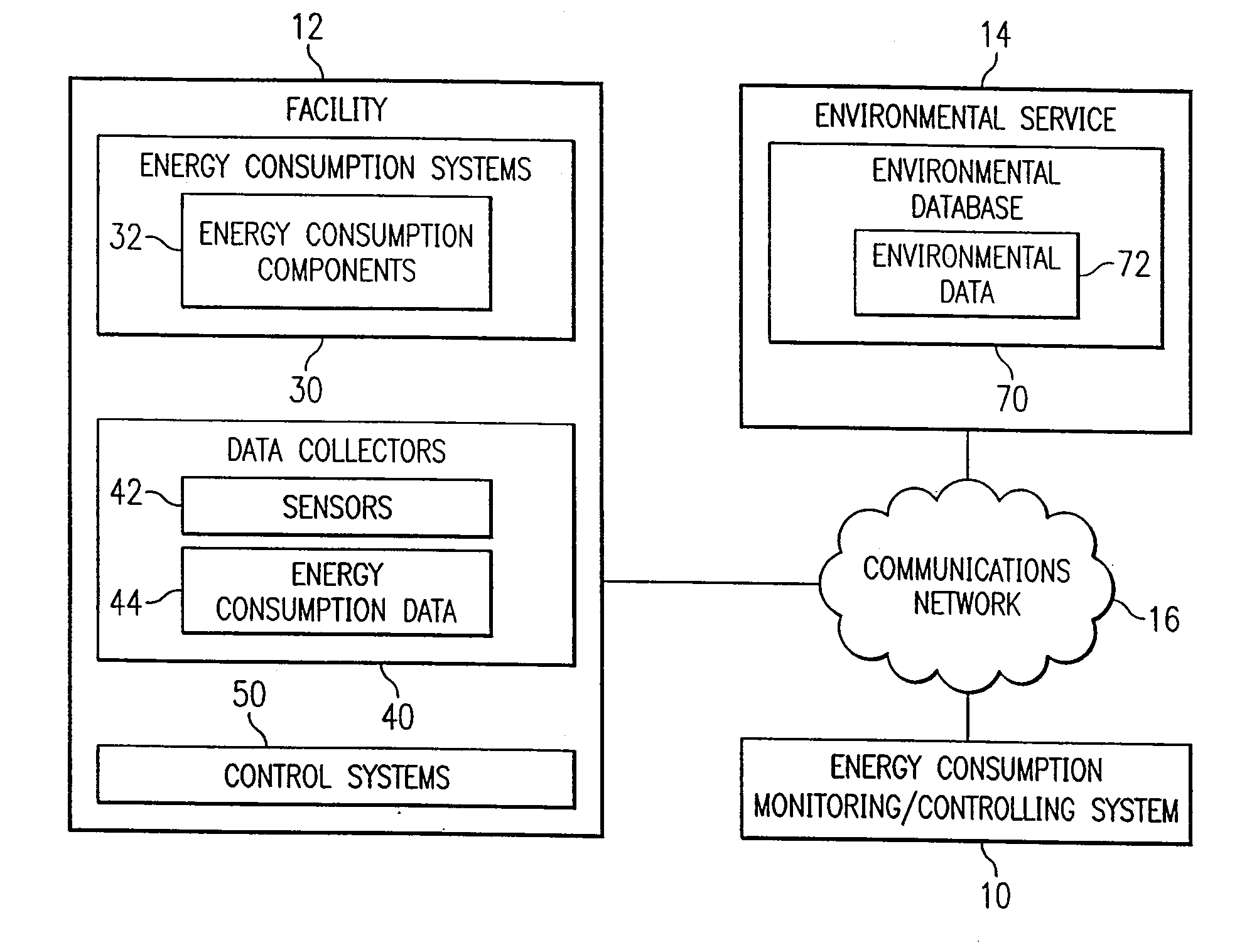
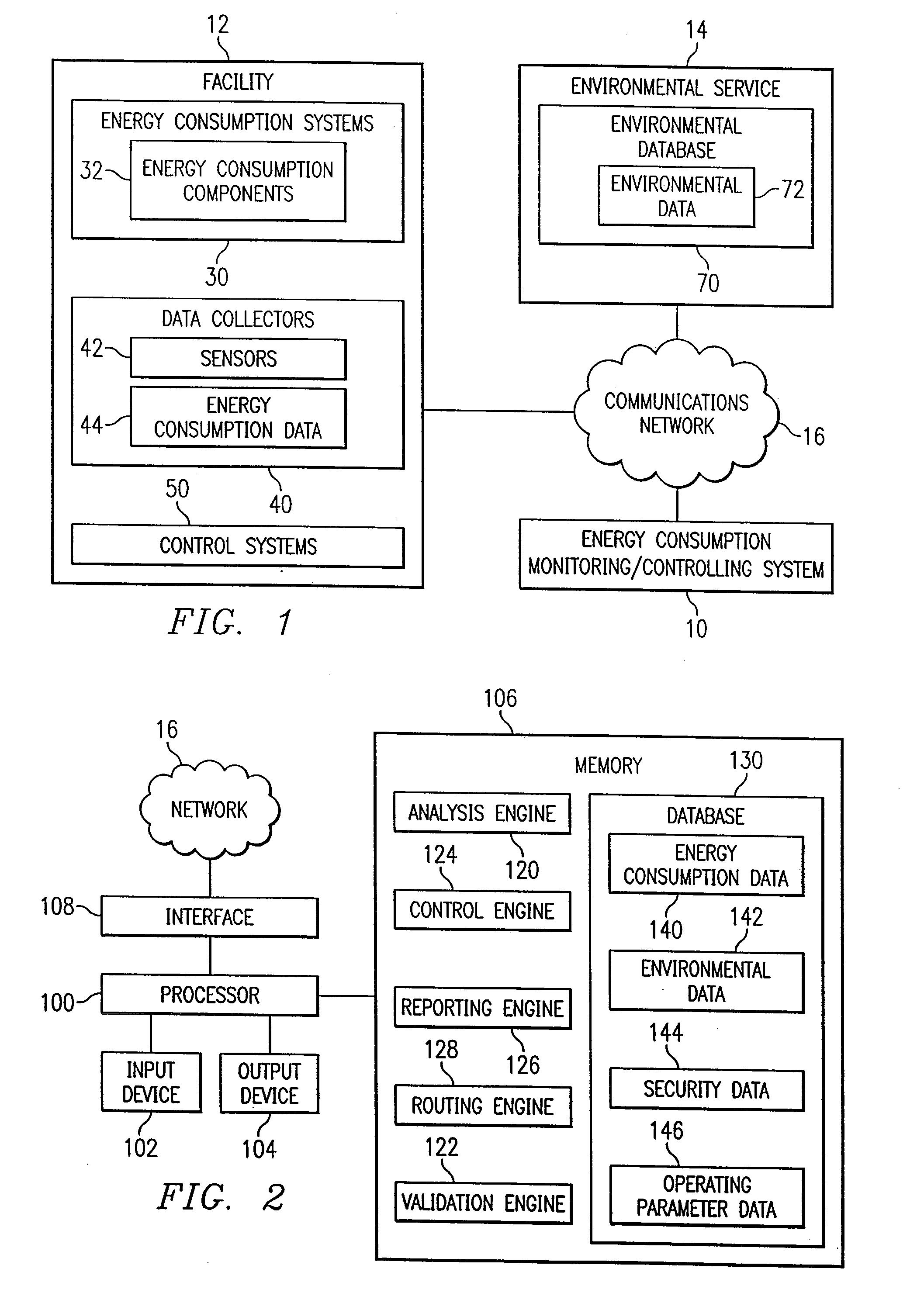
[0019]FIG. 1 is a block diagram in which a system 10 for remote monitoring and controlling of facility energy consumption in accordance with an embodiment of the present invention is illustrated. In the illustrated embodiment, the system 10 is coupled to a facility 12 and an environmental service 14 via a communications network 16. The communications network 16 may be different networks, or the same network, and may include any Internet, intranet, extranet, or similar communication network. The communications network 16 provides an electronic medium for transmitting and receiving information between the system 10, the facility 12, and the environmental service 14. However, it should be understood that other electronic and non-electronic modes of communication may also be used for transmitting and receiving information between the system 10, the facility 12, and the environmental service 14.

[0020]The facility 12 comprises a building, structure, location, worksite, plant, vicinity or ...


PUM


Abstract

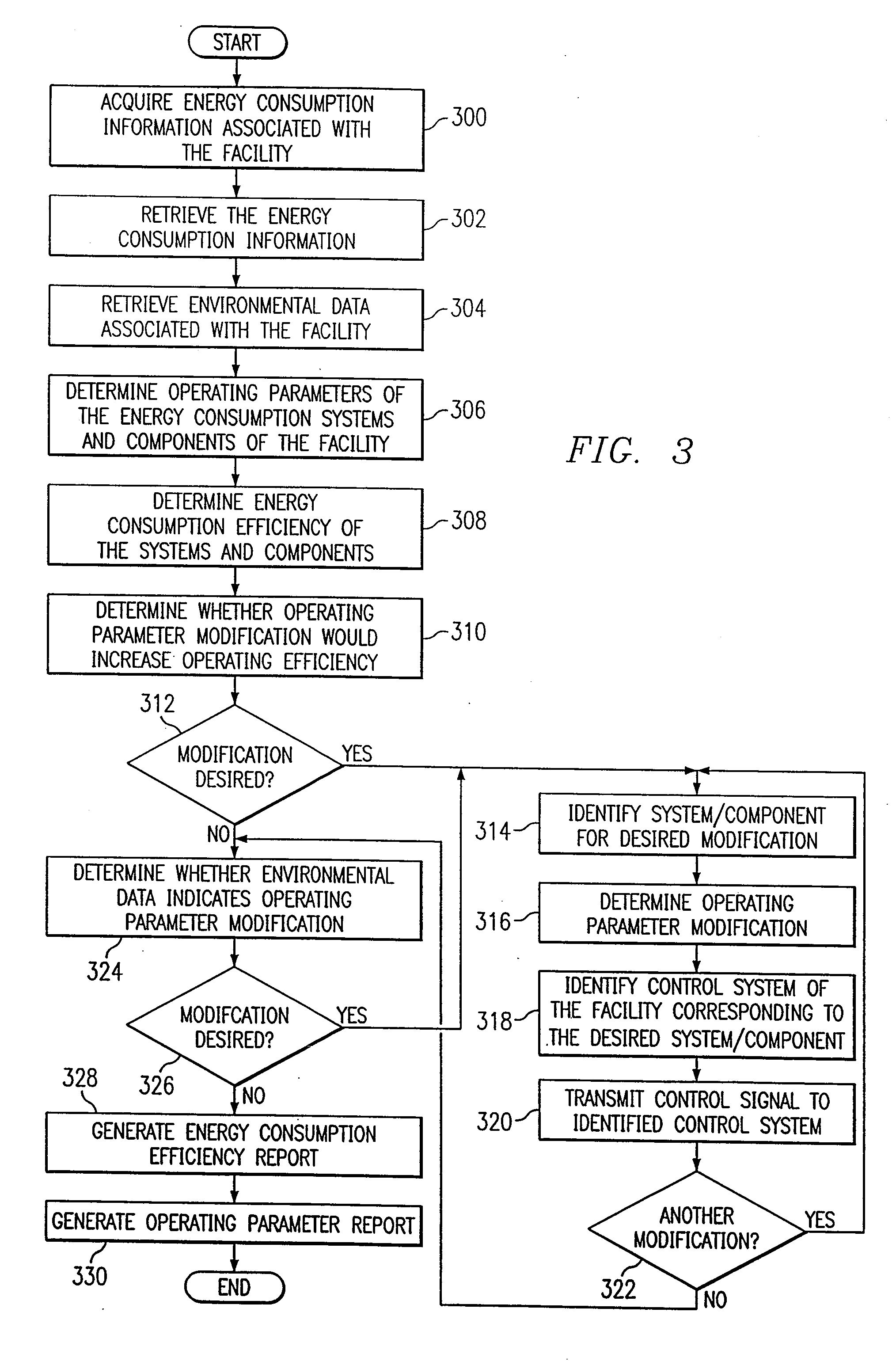
A method for remote monitoring and controlling of energy consumption of a facility includes receiving energy consumption data associated with the facility at a processor disposed remotely from the facility. The method also includes receiving environmental data associated with the facility. The method includes determining whether an operating parameter of an energy consumption system of the facility requires modification to increase efficiency using the energy consumption data and the environmental data. The method further includes automatically modifying the operating parameter of the energy consumption system corresponding to the required modification.

Description

RELATED APPLICATIONS[0001]This application is a continuation of U.S. application Ser. No. 10 / 004,988, filed Dec. 3, 2001, entitled “System and Method for Remote Monitoring and Controlling of Facility Energy Consumption,” now U.S. Pat. No. 7,356,548.TECHNICAL FIELD OF THE INVENTION[0002]This invention relates in general to the field of energy systems and, more particularly, to a system and method for remote monitoring and controlling of facility energy consumption.BACKGROUND OF THE INVENTION[0003]Schools, office buildings, homes, department stores, hospitals, and other types of facilities consume energy in varying amounts using a variety of different types of systems and components. For example, energy consumption systems and components may be used for environmental control, such as heating and cooling, for lighting, for security system applications, for computer usage applications, and for a variety of other energy consumption applications corresponding to the particular type of fac...

Claims


Application Information

Patent Timeline
Patent Type & Authority Applications(United States)
IPC IPC(8): G05B13/02
CPCH04L67/12H04L67/125H04L41/0816H04L41/0833
Inventor CULP, CHARLES H.CLARIDGE, DAVID E.HABERL, JEFFREY S.TURNER, WILLIAM D.
Owner TEXAS A&M UNIVERSITY
Learn More