Method for fail-safe transmission, safety switching device and control unit

a safety switching device and transmission method technology, applied in the field of failsafe transmission, can solve the problems of affecting the response time of the control system, affecting the accuracy of the transmission method,

Inactive Publication Date: 2012-11-27
SIEMENS AG
View PDF5 Cites 21 Cited by
  • Summary
  • Abstract
  • Description
  • Claims
  • Application Information

AI Technical Summary

Benefits of technology

[0009]The data to be safeguarded is not sent a further time on a separate data line as in the prior art but a first identifier is generated, a so-called hash value for the data to be safeguarded is transmitted by way of the second data line. This has the advantage that a sufficiently high level of data integrity is achieved without increasing the data volume per channel or per line. This method also advantageously allows the requirement of a short response time for a telegram reply from the transmitter to the receiver and vice versa to be met. These advantages are tangible in particular with small quantities of data, e.g. 16 bits of information, and at low baud rates (less than one MBaud).
[0010]In one advantageous embodiment a second identifier is generated for the second telegram from a second subset of the first telegram, which is different from the first subset. The identifiers are generally CRC values. CRC is an abbreviation for Cyclic Redundancy Check. The cyclic redundancy check is a method known from information technology for determining a check value for data in order to be able to identify errors during the transmission of data. By generating the second identifier, in other words a further CRC check value in the second data telegram, it is possible to increase data integrity still further. The CRC check value is thus lengthened to check for freedom from error.
[0011]For simplified and faster assignment of the telegrams at the receiver it is advantageous if a continuous number is generated for the second telegram. Assignment is further simplified if the continuous number is also generated for the first telegram for assignment of the telegrams at the receiver.
[0013]The first and second data line can now preferably be used as unshielded data lines during operation of a safety switching device at a control unit. In the case of stochastic or random transmission errors, e.g. due to EMC influences on the data lines; these errors can be identified and managed by the method. The probability of an error due to EMC interference is very high with unshielded data lines in particular. The data transmission method however now allows unshielded cables to be used for laying in the process automation industry for example, despite possible EMC interference. This is particularly advantageous, as these unshielded data lines are considerably more economical than shielded data lines. A further advantage is the use of the existing installation, which is generally fitted with unshielded cables / data lines.
[0015]It is also advantageous if the second means are embodied to generate a second identifier for the second telegram from a second subset of the first telegram, which is different from the first subset.
[0018]If the identifier of the information is longer than the information, it is advantageous to accommodate some of the identifier in the first telegram and the remainder of the identifier in the second telegram, so that both telegrams have the same length.

Problems solved by technology

According to the prior art with fail-safe systems or during the fail-safe transmission of data from a safety switching device to a higher-order control unit telegrams with a backup appendix are sent in duplicate according to IEC 61 784-3 Annex A, Model B and C. Since here the information content is transmitted in a redundant manner in two telegrams on two different data channels or with a time offset one after the other on one data channel to the receiver or to the control unit, this transmission method has the disadvantage of a lower level of error detection in relation to data volume.
The longer the checksum, the higher the level of error detection.
However a long checksum lengthens the telegram, having an adverse effect on the response times of the control system.

Method used


Image

  • Method for fail-safe transmission, safety switching device and control unit
  • Method for fail-safe transmission, safety switching device and control unit
  • Method for fail-safe transmission, safety switching device and control unit

Examples


Embodiment Construction

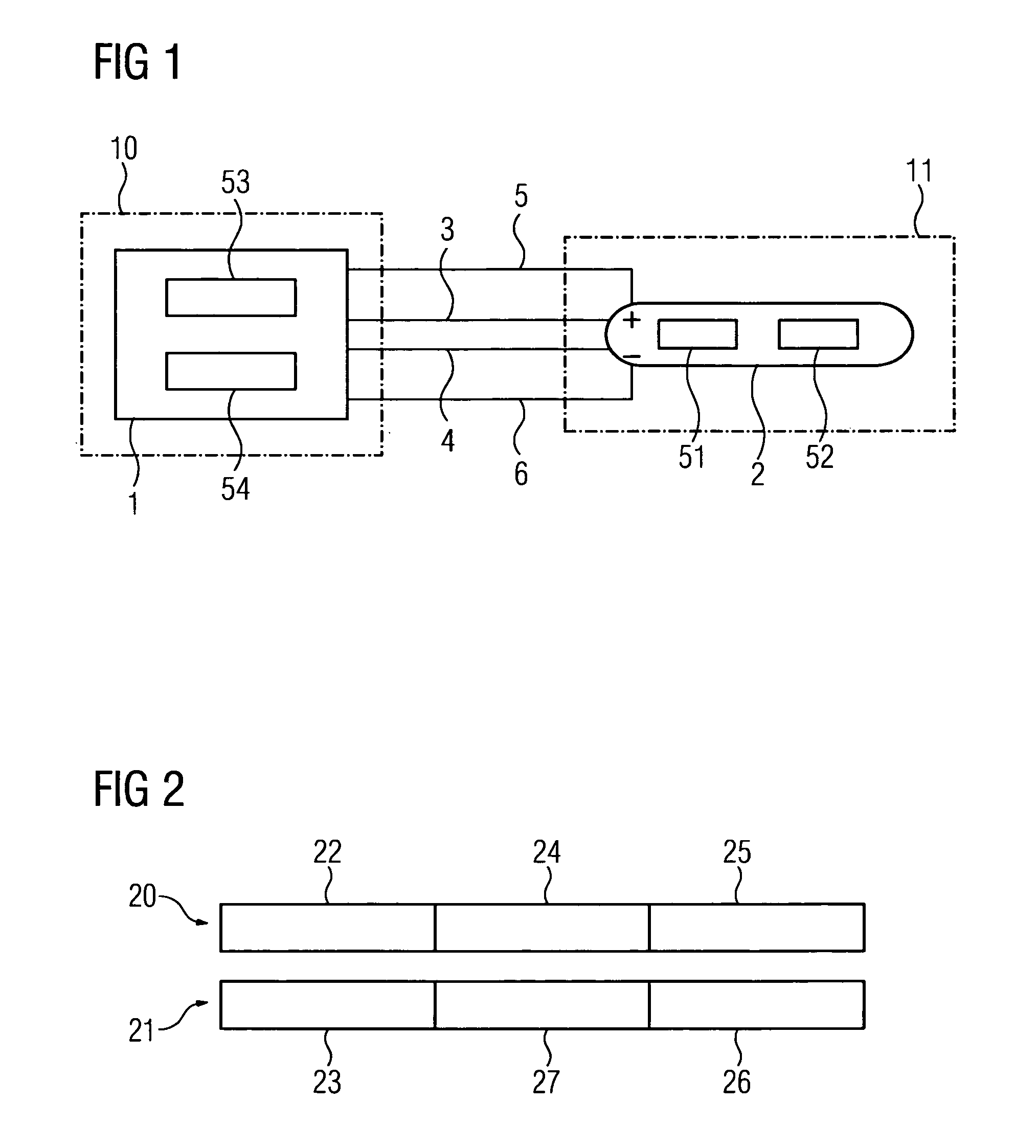
[0023]FIG. 1 shows a safety switching device 11 connected to a control unit 10. The control unit 10 essentially has a transmitter 1. It is not restricted here to this transmitter 1 only having the transmit function, it can likewise switch to the receive mode of operation. If the control unit 10 with its transmitter 1 operates in the transmit mode of operation, a receiver 2 is available in the safety switching device 11 to receive the sent information from the transmitter 2 in the control unit 10. The transmitter 1 is connected by way of four lines / wires to the receiver 2. A first line 3 (which together with the line 6 forms a data line) and a second line 4 (which together with line 6 forms a second data line) allow communication between the transmitter 1 and the receiver 2. The safety switching device 11 is supplied with an operating voltage by way of the supply voltage lines 5, 6. The control unit 10 is embodied with a third means 53 to transmit and receive information. This third ...


PUM


Abstract

A method for fail-safe transmission of information between a transmitter and a receiver is disclosed. At least two telegrams relating to the information are transmitted as a first telegram via a first channel and a second telegram via a second channel from the transmitter to the receiver. To identify an error affecting the information during transmission, a first identifier is generated from a first subset of the first telegram being used at the receiver to identify the information contained in the first telegram. This method is used for communication from a safety switching device to a control unit.

Description

CROSS REFERENCE TO RELATED APPLICATIONS[0001]This application claims priority of European Patent Application No. 08007059.2 EP filed Apr. 9, 2009, which is incorporated by reference herein in its entirety.FIELD OF INVENTION[0002]The invention relates to a method for the fail-safe transmission of information between a transmitter and a receiver, with at least two telegrams relating to the information being transmitted as a first telegram by way of a first channel and a second telegram by way of a second channel from the transmitter to the receiver. The invention also relates to a method for operating a safety switching device at a control unit. The invention also relates to a safety switching device suitable for the fail-safe transmission of information to a control unit and vice versa, with a first data line for a first channel and a second data line for a second channel, with first means for transmitting / receiving a first telegram relating to the information on the first channel an...

Claims


Application Information

Patent Timeline
Patent Type & Authority Patents(United States)
IPC IPC(8): H03M13/00H04L1/00G08C25/00
CPCH04L1/008H04L1/06H04L1/0064
Inventor BARTHEL, HERBERTSTRIPF, WOLFGANG
Owner SIEMENS AG
Why Eureka
Try Eureka