Method and Arrangements for Coding Audio Signals

Active Publication Date: 2009-01-08
UNIFY GMBH & CO KG
View PDF3 Cites 10 Cited by
  • Summary
  • Abstract
  • Description
  • Claims
  • Application Information

AI Technical Summary

Benefits of technology

[0011]The object of the present invention is to specify a method for forming an excitation signal for an audio synthesis filter, which allows a further reduction of the transmission rate and/or an improvement in the audible impression and a reduction

Problems solved by technology

In many modern communication systems and in particular in mobile communication systems only limited transmission bandwidths are available for real-time audio transmissions, such as voice or music transmissions for example.
The search through two code books to be carried out according to the

Method used


Image

  • Method and Arrangements for Coding Audio Signals
  • Method and Arrangements for Coding Audio Signals
  • Method and Arrangements for Coding Audio Signals

Examples


Example

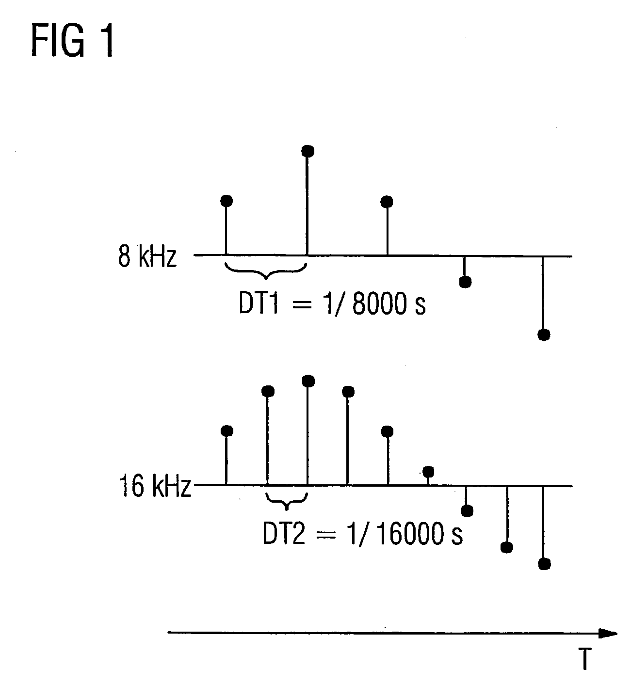
[0036]FIG. 1 shows an audio signal sampled at different exemplary sampling rates. Individual sampled values are shown here as dots, having different amplitudes shown by vertical lines. The different sampling rates are illustrated by different temporal sampling intervals between the sampled values. Both partial figures have a common time axis T.

[0037]The upper partial figure shows the audio signal sampled at a sampling rate of 8 kHz for example. The sampling rate of 8 kHz corresponds to a sampling interval DT1 of 1 / 8000 s. Audio signals essentially up to a frequency of 4 kHz can be shown by the sampled values sampled at a sampling rate of 8 kHz according to a fundamental sampling theorem. This frequency range is hereafter referred to as narrowband.

[0038]The lower partial figure illustrates the audio signal sampled at a sampling rate of 16 kHz. In accordance with the sampling rate, which is double the sampling rate of the upper partial figure, the sampling interval DT2 in the lower pa...


PUM


Abstract

According to the invention, an excitation signal is generated as a result of sampled excitation values in order to excite an audio synthesis filter, the generated sampled excitation values being continuously stored in an adaptive codebook. A noise generator is provided which continuously generates random sampled values. A sequence of the stored sampled excitation values is selected from the adaptive codebook based on a fed audio fundamental frequency parameter by means of which a time gap between the sequence that is to be selected and the actual time reference is predefined. The excitation signal is generated by mixing the selected sequence with a random sequence encompassing actual random sampled valued of the noise generator.

Description

CROSS REFERENCE TO RELATED APPLICATIONS[0001]This application is the US National Stage of International Application No. PCT / EP2006 / 000811, filed Jan. 31, 2006 and claims the benefit thereof, which is incorporated by reference herein in their entirety.FIELD OF THE INVENTION[0002]The invention relates to a method and arrangements for coding audio signals. In particular the invention relates to a method and an excitation signal generator for forming an excitation signal to excite an audio synthesis filter as well as an audio signal encoder and an audio signal decoder.BACKGROUND OF THE INVENTION[0003]In many modern communication systems and in particular in mobile communication systems only limited transmission bandwidths are available for real-time audio transmissions, such as voice or music transmissions for example. In order to transmit as many audio or voice channels as possible in real time by way of a transmission link with limited bandwidth, as via a radio network for example, pr...

Claims


Application Information

Patent Timeline
IPC IPC(8): G10L19/12G10L21/02G10L19/00G10L21/038
CPCG10L21/038G10L19/12G10L2019/0001
Inventor GEISER, BERNDJAX, PETERSCHANDL, STEFANTADDEI, HERVE
Owner UNIFY GMBH & CO KG
Why Eureka
Try Eureka