Rolling door retainer

a technology for retaining devices and doors, applied in door/window fittings, construction, building components, etc., can solve the problems of large damage and principal damage to aircraft in hangars, and achieve the effect of preventing door displacement and being easy to install

Inactive Publication Date: 2009-01-15
GRAY BILL M
View PDF31 Cites 1 Cited by
  • Summary
  • Abstract
  • Description
  • Claims
  • Application Information

AI Technical Summary

Benefits of technology

[0007]It would be very desirable to provide a means for preventing door displacement from their guiding tracks unless needed for door replacement and repair. Therefore, it is an object of the invention to provide a door retainer which prevents vertical displacement of the door and its rollers from its supporting track and at the same time permits the doors to be used without interference.
[0008]It is another object of the invention to provide such a door retainer which is easily installed on existing doors when they are in position on their tracks.
[0009]It is an object of the invention to provide a door retainer which prevents vertical displacement of the door and its rollers from the supporting track.
[0010]These and other objects of the invention are attained by a door retainer for aircraft hangar doors in which vertical movement of the door rollers to raise them off of their supporting tracks is prevented by a vertical retainer bolt adjustable to project above the upper top edge of the doors to engage the top guiding channel of the doors to limit upward door movement that might otherwise occur in strong or high wind conditions or during earthquakes. Such adjustment does not hinder normal opening and closing of the doors. The door retaining bolts are adjustable to a retracted position to permit door removal or replacement when required.

Problems solved by technology

Hurricanes and high winds are known to cause such doors to be lifted off of the tracks and to fall against expensive aircraft causing much damage.
Examination of aircraft hangars damaged following hurricanes that impacted Florida in 2004 found that a principal damage to aircraft in hangars was caused by the doors of the hangars which high winds caused to be displaced from their intended position and crash against the airplane housed in the hangar.

Method used


Image

  • Rolling door retainer
  • Rolling door retainer
  • Rolling door retainer

Examples


Embodiment Construction

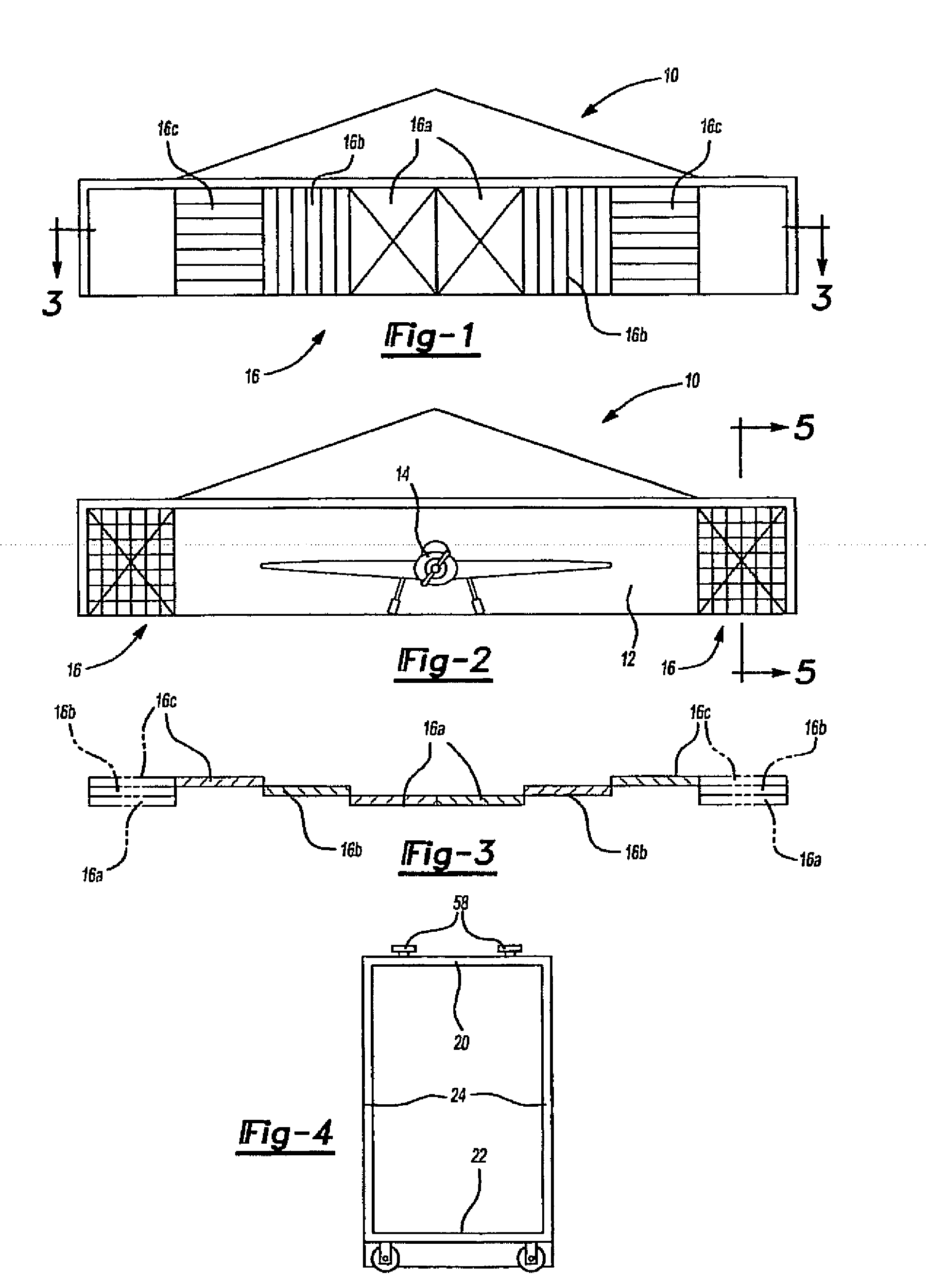
[0020]The rolling doors to which the retainer of the present invention are related are shown in FIGS. 1 through 3. There are a wide variety of rolling and sliding doors and windows in use but those used for aircraft hangars such as designated at 10 must cover wide openings 12 to accommodate large wing spans of airplanes 14. Consequently, they are used in larger numbers of four: six, eight or more to cover the hangar wide door opening. The present description will make reference to three doors at each side of an opening for a total of six doors.

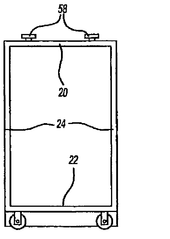
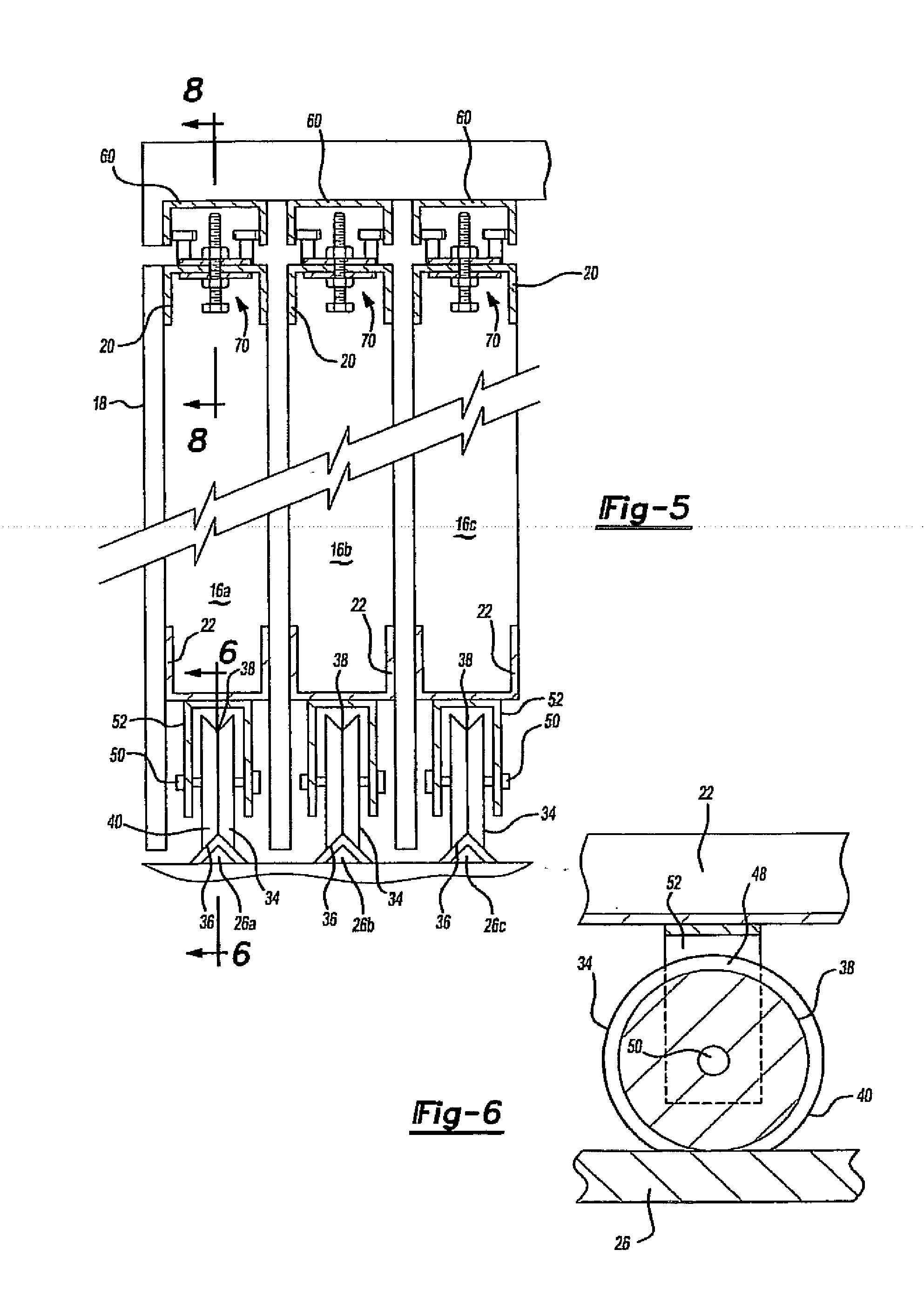
[0021]Such doors are designated generally at 16 and typically are fabricated of light metal channel members defining the perimeter of the door and which can best be seen in FIG. 5 with at least one side of the doorframe being covered with a light metal panel 18 often of a corrugated configuration. Each door typically has an upper channel member 20, a lower horizontal frame member 22 and opposed vertically disposed door edge members 24 as seen ...


PUM


Abstract

A retainer for aircraft hangar doors in which vertical movement of doors is adjustably limited to allow sufficient movement to permit door removal from their supporting tracks or to prevent such undesirable displacement during high wind conditions as experienced during hurricanes and tornadoes or violent earth motions during earthquakes. The retainer in its retaining position does not obstruct normal opening and closing of the doors and is economical to manufacture and install.

Description

CROSS-REFERENCE TO RELATED APPLICATIONS[0001]This application is a continuation of U.S. patent application Ser. No. 11 / 079,700 filed on Mar. 14, 2005.FIELD OF THE INVENTION[0002]This invention relates to retainers for rolling doors and in particular to rolling doors for aircraft hangars in which relatively wide openings are closed by multiple doors arranged at opposite sides of the door opening to be stacked in a door open position at one side of the opening and to slightly overlap each other in a door closed position.BACKGROUND OF THE INVENTION[0003]Sliding or rolling doors and windows are commonly used in household and commercial buildings usually with a pair of doors closing an enclosure. Such doors typically have their own upper and lower guide tracks and are removable by vertical movement upwardly a small amount into the upper guide track to dislodge the lower portion of the door and permit its removal. Various devices have been developed to prevent such movement but their inst...

Claims


Application Information

Patent Timeline
Patent Type & Authority Applications(United States)
IPC IPC(8): E06B3/42
CPCE06B3/01
Inventor GRAY, BILL M.
Owner GRAY BILL M
Why Eureka
Try Eureka