
Refrigeration System

a refrigeration system and compressor technology, applied in the direction of machines/engines, liquid fuel engines, light and heating apparatus, etc., can solve the problems of large the likely change in compression torque of the drive shaft, so as to reduce the vibration and noise of the compressor, reduce the change in compression torque in the non-operation mode of the cylinder, and reduce the effect of vibration and nois

Active Publication Date: 2009-01-15
DAIKIN IND LTD
View PDF9 Cites 22 Cited by
  • Summary
  • Abstract
  • Description
  • Claims
  • Application Information

AI Technical Summary

Benefits of technology

The invention is about a refrigeration system that reduces the change in the compression torque of the drive shaft in the cylinder non-operating mode and the two-stage compression mode. The system includes a compressor with multiple compression chambers that cycle to change capacity and compress refrigerant. The compressor operates in a parallel compression mode or a cylinder non-operating mode. In the parallel compression mode, refrigerant is compressed in a single stage in each chamber, and in the cylinder non-operating mode, refrigerant is compressed in a single stage in each chamber while the other chambers are not operating. This results in a more stable refrigerant pressure and reduces the change in the compression torque of the drive shaft. The technical effect of the invention is to improve the stability and efficiency of the refrigeration system.

Problems solved by technology

Thus, when the change in the refrigerant pressure in the compression chamber of the first compression mechanism becomes large, the compression torque of the drive shaft changes to a large degree.
Thus, also in the two-stage compression mode, when the change in the refrigerant pressure in the compression chamber of the first compression mechanism becomes large, the compression torque of the drive shaft is likely to change.

Method used


Image

  • Refrigeration System
  • Refrigeration System
  • Refrigeration System

Examples


embodiment 1

Effects of Embodiment 1

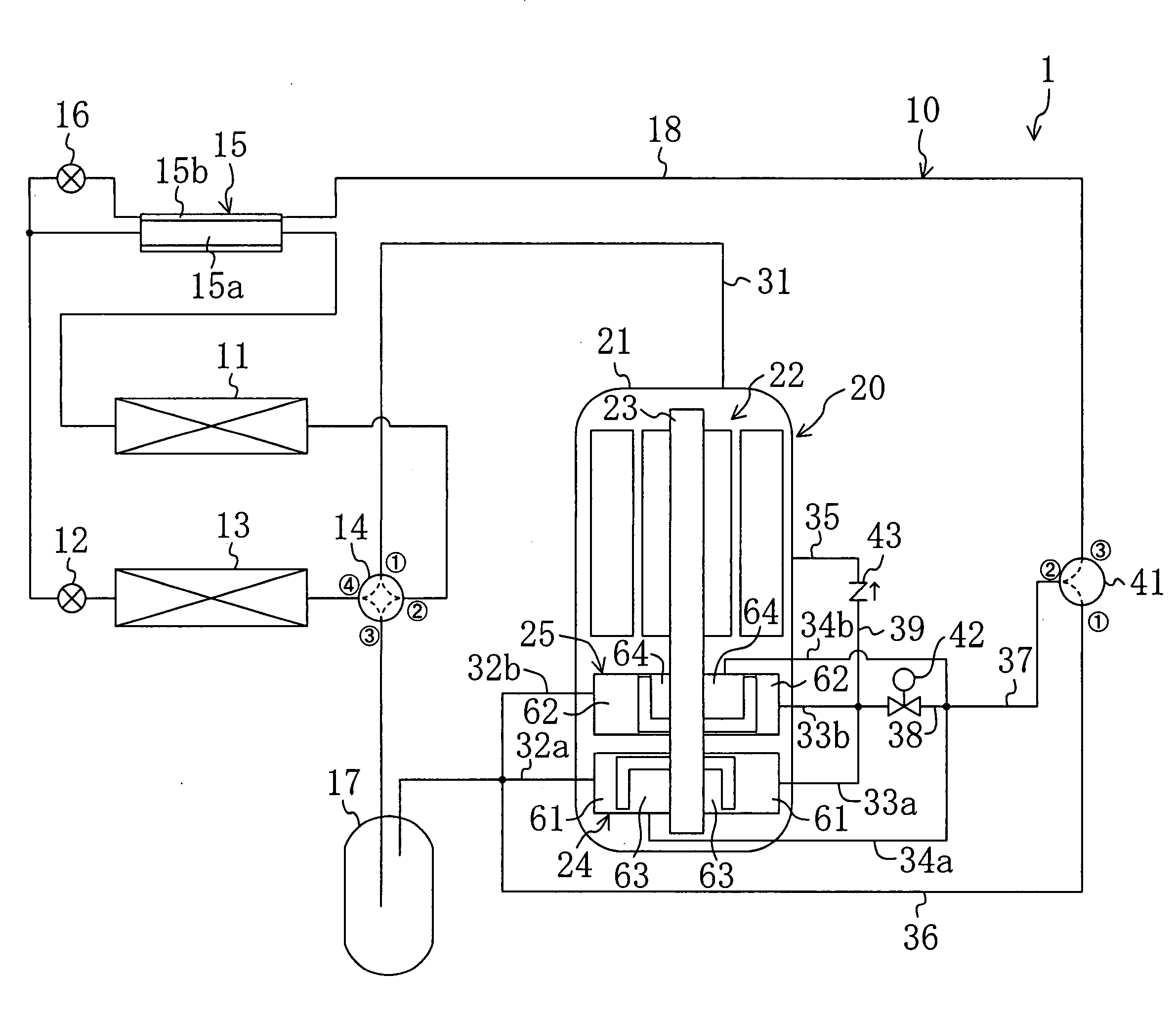
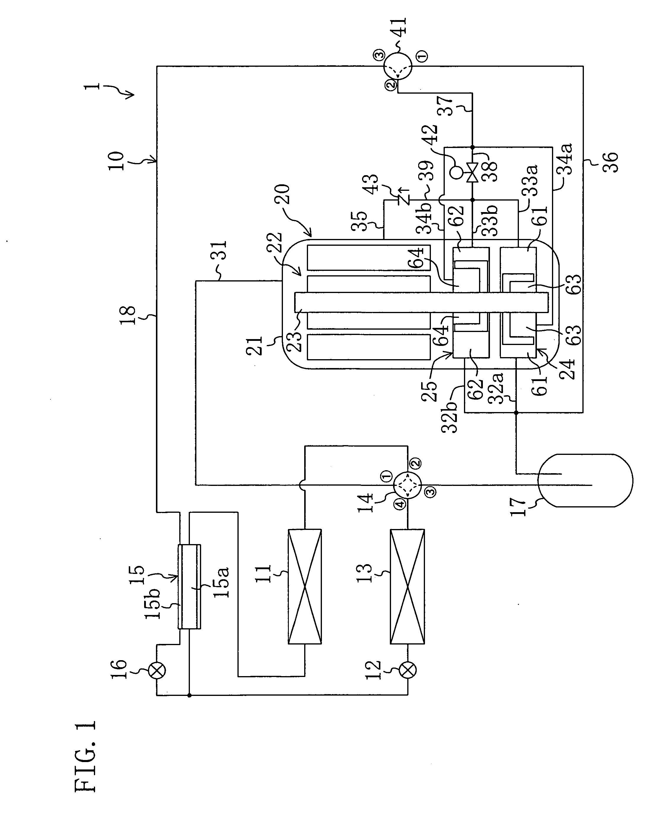
[0134]As described previously, in Embodiment 1, the compressor (20) includes a first compression mechanism (24) having two compression chambers (61, 63) and a second compression mechanism (25) having two compression chambers (62, 64), wherein the first compression chamber (61) and the second compression chamber (62) differ in the phase of capacity changing cycle from each other by 180° and the third compression chamber (63) and the fourth compression chamber (64) also differ in the phase of capacity changing cycle from each other by 180°.

[0135]Therefore, in the cylinder nonoperating mode, the third compression chamber (63) and the fourth compression chamber (63) can be made different in the phase of changing cycle of refrigerant pressure from each other by 180°, thereby reducing the change in compression torque in the cylinder nonoperating mode. Hence, in the cylinder nonoperating mode that is relatively likely to invite increased vibration and noise, the comp...

embodiment 2

Effects of Embodiment 2

[0161]As described previously, in Embodiment 2, the compressor (20) includes first to fourth compression mechanisms (24, 25, 26, 27) each having one compression chamber (61, 62, 63, 64), wherein the first compression chamber (61) and the second compression chamber (62) differ in the phase of capacity changing cycle from each other by 180° and the third compression chamber (63) and the fourth compression chamber (64) also differ in the phase of capacity changing cycle from each other by 180°.

[0162]Therefore, like Embodiment 1, in the cylinder nonoperating mode, the phase at the maximum refrigerant pressure in the third compression chamber (63) and the phase at the maximum refrigerant pressure in the fourth compression chamber (64) can be made different from each other by 180°, thereby reducing the compression torque in the cylinder nonoperating mode. Furthermore, also in the two-stage compression mode of Embodiment 2, the phase at the maximum refrigerant pressu...


PUM


Abstract

A compressor (20) is provided with compression mechanisms (61, 62) to have four compression chambers (61, 62, 63, 64) in total. In the compressor (20), the first compression chamber (61) and the second compression chamber (62) differ in the phase of capacity changing cycle from each other by 180° and the third compression chamber (63) and the fourth compression chamber (64) also differ in the phase of capacity changing cycle from each other by 180°. In a cylinder nonoperating mode, refrigerant is compressed in a single stage in each of the first compression chamber (61) and the second compression chamber (62) while the refrigerant compression operation is halted in the third compression chamber (63) and the fourth compression chamber (64). In a two-stage compression mode, refrigerant compressed in a single stage in each of the first compression chamber (61) and the second compression chamber (62) is further compressed in the third compression chamber (63) and the fourth compression chamber (64).

Description

TECHNICAL FIELD[0001]This invention relates to refrigeration systems including a compressor with a plurality of compression chambers and operable in a refrigeration cycle.BACKGROUND ART[0002]Refrigeration systems including a refrigerant circuit operating in a refrigeration cycle by circulating refrigerant therethrough have conventionally been widely used, such as for air conditioners.[0003]For example, Patent Document 1 discloses an air conditioner including a twin-cylinder compressor. The refrigerant circuit of this air conditioner is provided with a compressor, an indoor heat exchanger, an expansion valve, an outdoor heat exchanger and other components. The compressor includes a drive motor, a drive shaft that can be driven by the drive motor, and first and second compression mechanisms connected to the drive shaft. The two compression mechanisms are composed of so-called rotary compression mechanisms in which a piston eccentrically rotates in the cylinder chamber in a cylinder. I...

Claims


Application Information

Patent Timeline
Patent Type & Authority Applications(United States)
IPC IPC(8): F25B1/10
CPCF04C18/02F04C18/045F04C18/322F04C23/001F04C23/008F25B2400/13F04C2270/03F04C2270/12F25B1/04F25B2400/075F04C29/0035F04C23/00F04C28/02
Inventor YAMAGUCHI, TAKAHIROISHIKAWA, SATOSHIYAMADA, MASAHIROFURUSHO, KAZUHIRO
Owner DAIKIN IND LTD
Learn More