Sheet-metal bending machine, preferentially hydro-powered machine, and a method of its operation

a technology of bending machine and bending plate, which is applied in the direction of forging/hammering/hammering apparatus, forging/hammering/pressing machine, etc., can solve the problems of insufficient space for metal sheet handling, inability to laterally add other segments, and small opening width, so as to achieve good handling of sheets and large angular range of bending

Active Publication Date: 2009-01-15
HIRSCHEWALD LLC +1
View PDF6 Cites 5 Cited by
  • Summary
  • Abstract
  • Description
  • Claims
  • Application Information

AI Technical Summary

Benefits of technology

[0006]The present structure, including the related method of its operation, provides a sheet-metal bending machine, preferentially with a hydraulic drive, that can process even relatively large sheets with a relativel

Problems solved by technology

A smaller opening angle would not provide a sufficient space for metal sheet handling in most practical cases of sheet-metal bending, especially during bending or turning and removing sheets from the machine.
Smaller opening widths would not provide a sufficient space for sheet-metal handling in most practical cases, especially during bending or turning and removing sheets from the machine.
Generally, it would be possible to physically create such an axis as a pair of ax

Method used


Image

  • Sheet-metal bending machine, preferentially hydro-powered machine, and a method of its operation
  • Sheet-metal bending machine, preferentially hydro-powered machine, and a method of its operation
  • Sheet-metal bending machine, preferentially hydro-powered machine, and a method of its operation

Examples


Embodiment Construction

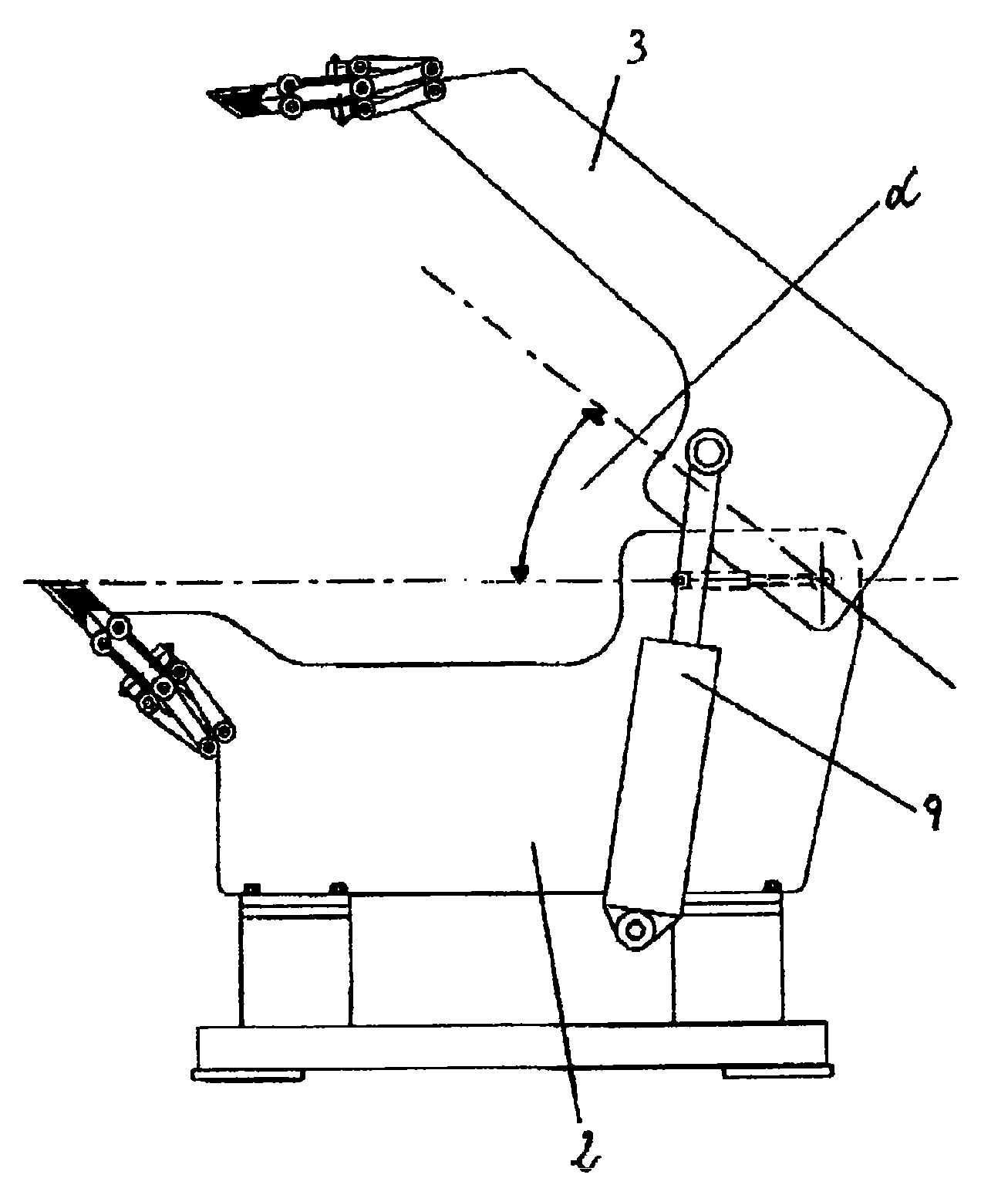
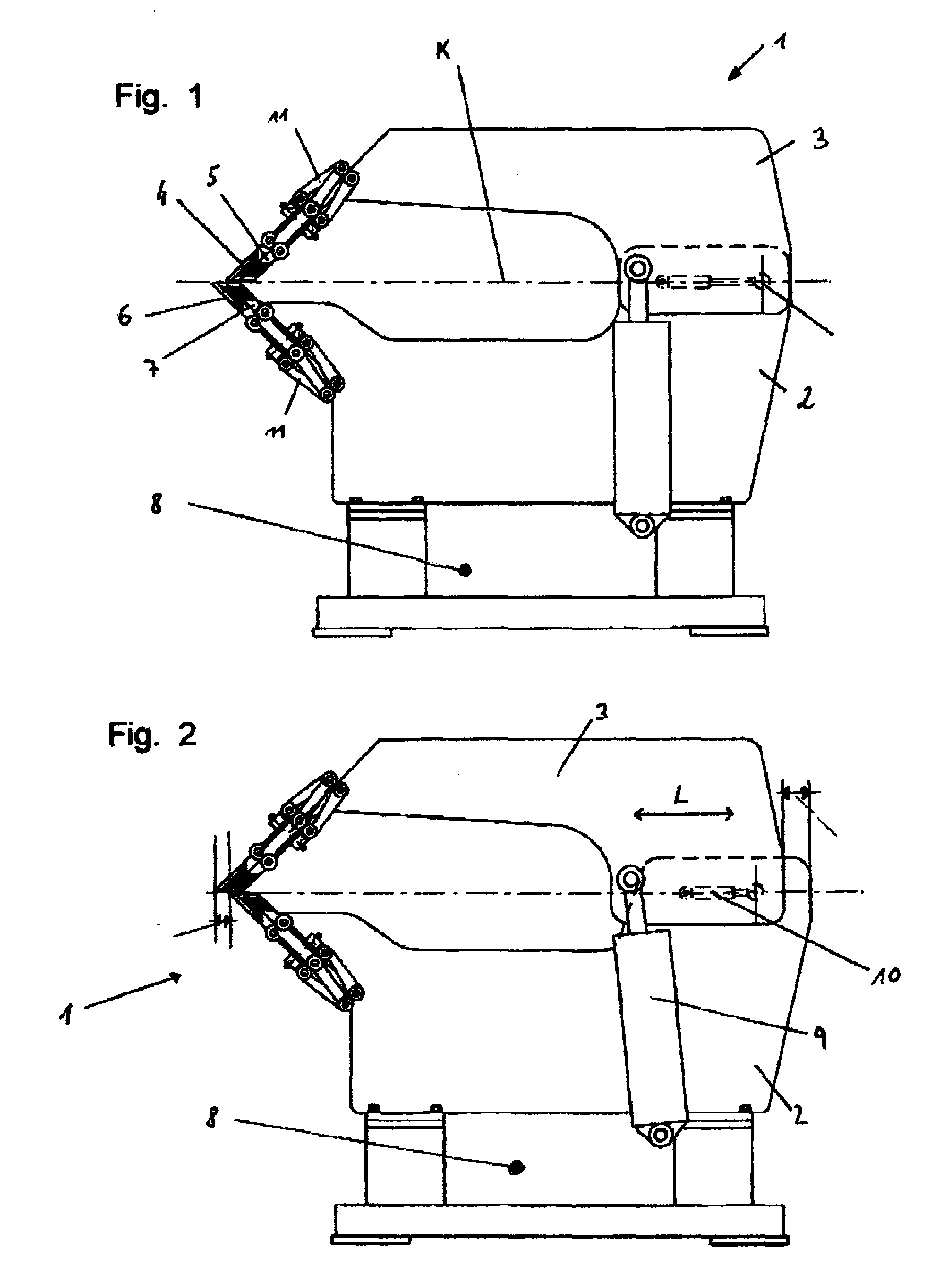
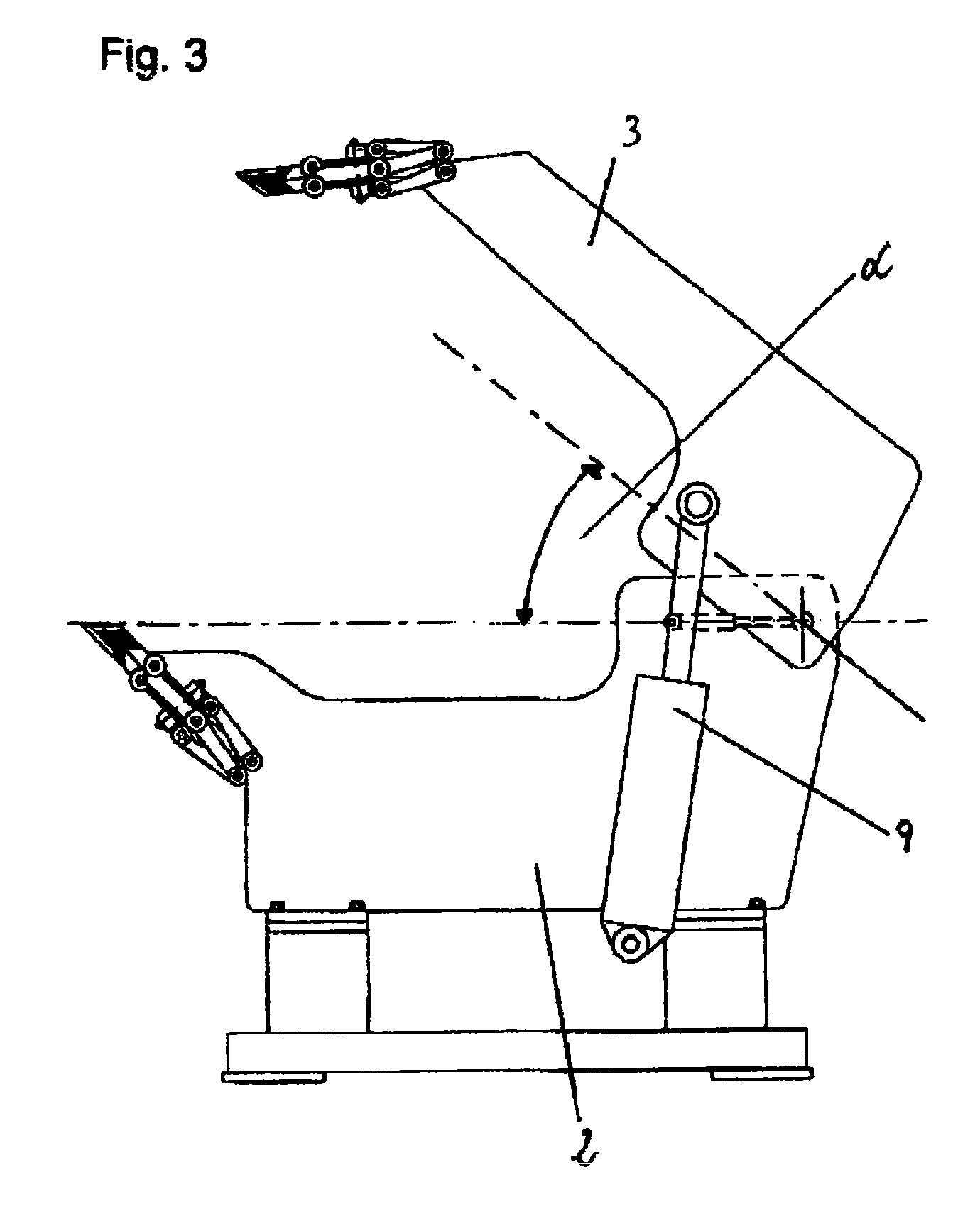
[0015]The sample embodiment of the invention presents a sheet-metal bending machine designed in accordance with the present invention, namely in a version where the upper machine part is suspended rotationally on the lower machine part. The other basic alternative, where the upper machine part can be separated from the lower machine part in a parallel position by shifting in a guide in the vertical direction is not shown here. This other alternative appears to be a little more complicated from the structural point of view, but as regards the effect, it is as functional as the first basic alternative. The presented sample embodiment represents, within the first basic alternative, its version where the mutual horizontal shift of the processing tools is achieved through sliding mounting of the upper machine part in the lower machine part.

[0016]Thus, in the presented sample embodiment, the bending machine 1 contains the lower machine part 2 and the upper machine part 3 mounted on it in ...


PUM

PropertyMeasurementUnit
Angleaaaaaaaaaa
Angleaaaaaaaaaa
Angleaaaaaaaaaa

Abstract

The invention deals with a sheet-metal bending machine containing a lower machine part and an upper machine part mounted on it in a movable way where on either of the upper and lower machine part there is a pair of working tools designed as a bending arm and a holding arm where the principle is that the upper machine part (3), or at least the pair of the working tools connected to it, is, in relation to the lower machine part (2), or at least in relation to the pair of the working tools connected to it in the feeding direction (L) of the processed metal sheet (14), mounted in a mutually horizontally sliding bond.

Description

TECHNICAL FIELD[0001]The invention deals with sheet-metal bending machines containing a lower fixed part and a movable upper part over the lower part while on either of the parts there is a movable bending device and a fixed holding device.BACKGROUND ART[0002]At present, sheet-metal bending machines are known that bend sheets in various directions while during the bending the processed object does not have to rotate between individual bending steps. For this purpose in the existing machines the sheet-metal is clamped between the upper and lower holding arm and being clamped this way it is bent or folded either from the top by the upper bending device or arm or from the bottom by the lower bending device or arm. A disadvantage of the operation of the machines of this type consists in the fact that until the moment of bending the inactive bending arm must be away from the bending space, which is achieved by turning or shifting of the arm that is inactive at the particular moment, e.g....

Claims


Application Information

Patent Timeline
IPC IPC(8): B21D11/00B21C51/00
CPCB21D5/042B21D5/04
Inventor FRANZE, REINHARD
Owner HIRSCHEWALD LLC
Why Eureka
Try Eureka