Threading device of sewing machine

Inactive Publication Date: 2009-01-15
JUKI CORP
View PDF3 Cites 5 Cited by
  • Summary
  • Abstract
  • Description
  • Claims
  • Application Information

AI Technical Summary

Benefits of technology

[0010]It is an object of the present invention to provide a threading device for a sewing machine having a plurality of needl

Problems solved by technology

According to the related art threading devices described above, however, a needle with respect to which the threading shaft or the threading member is set cannot be visually checked reliably after a switching operation unless the threading lever or an operation knob is actually operated to

Method used


Image

  • Threading device of sewing machine
  • Threading device of sewing machine
  • Threading device of sewing machine

Examples


first exemplary embodiment

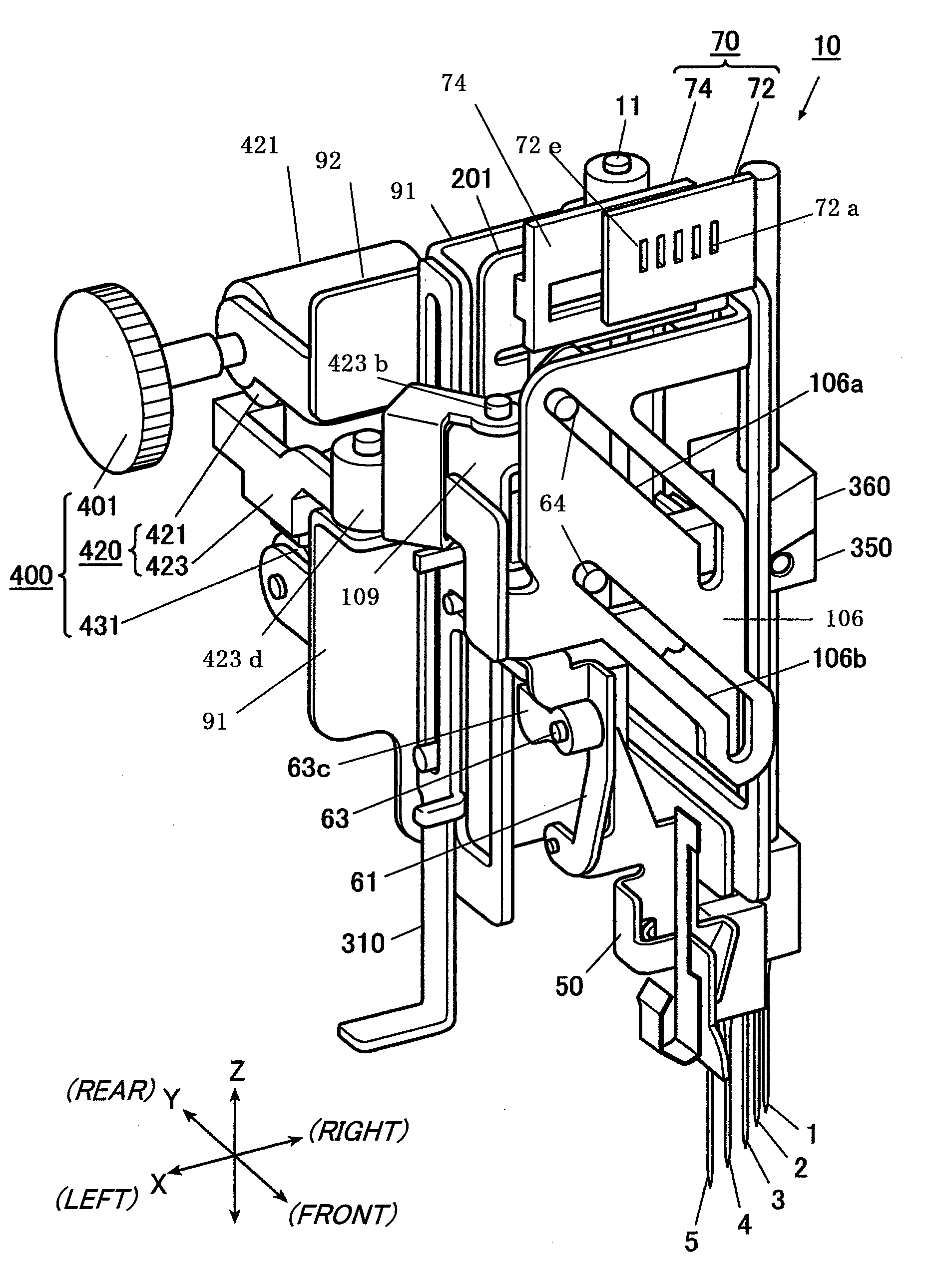
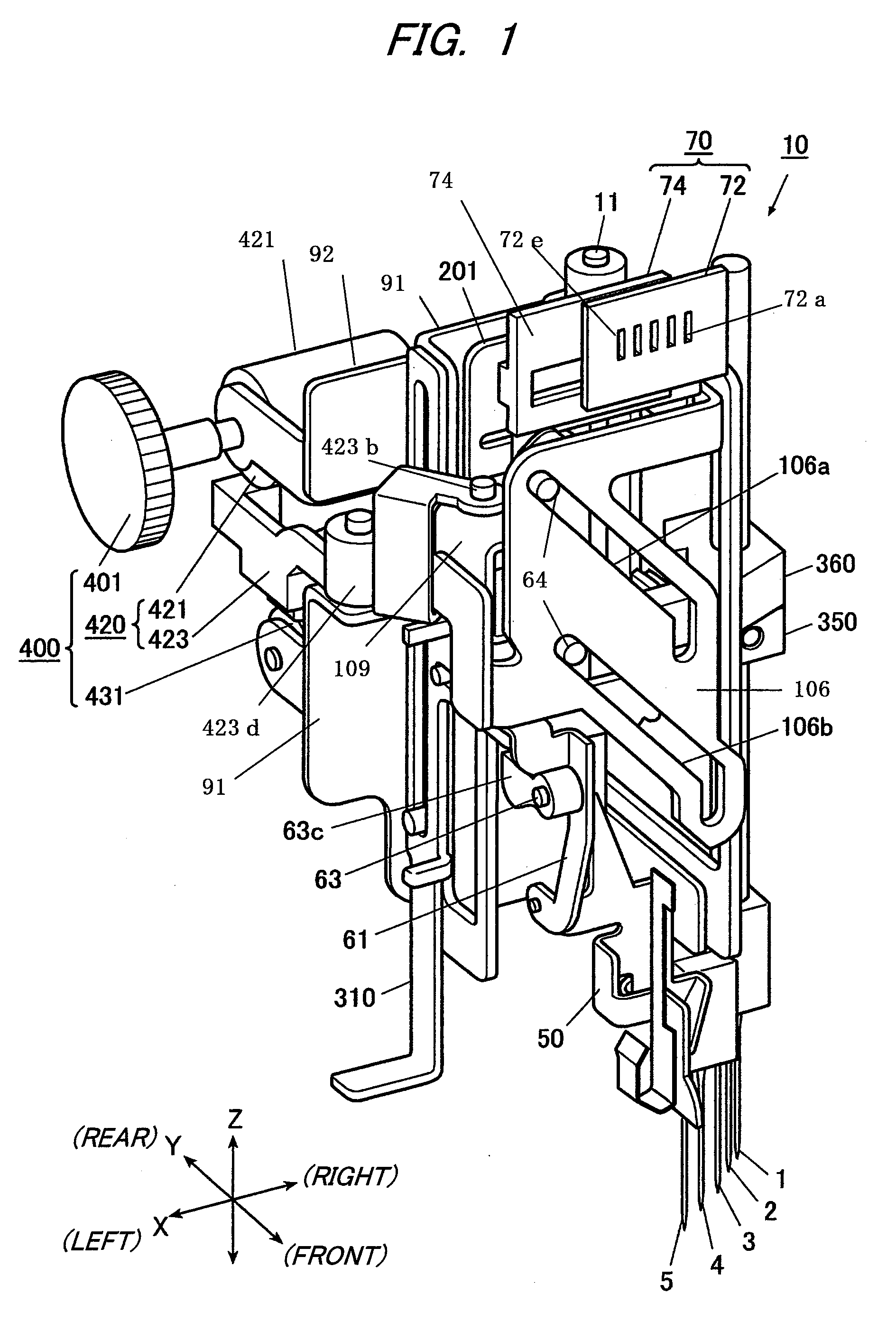
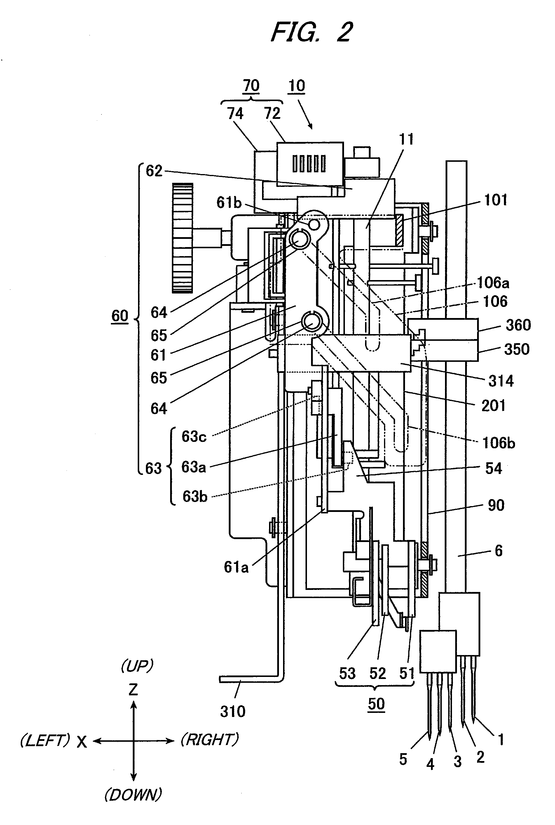
[0057]A threading device 10 of a sewing machine according to a first exemplary embodiment will be described with reference to FIGS. 1 to 18.

[0058]The sewing machine mounting the threading device 10 thereon can selectively implement an overlock stitch and a cover stitch and has the needle bar 6 capable of attaching five needles 1-5. Two needles 1 and 2 are used for the overlock stitch and three needles 3, 4 and 5 are used for the cover stitch. The needles 1, 2 of a first group and the needles 3, 4, 5 of a second group are parallel with the first direction respectively and are disposed with an offset in a second direction.

[0059]The threading device 10 is disposed in an arm portion of the sewing machine adjacently to the needle bar 6.

[0060]The threading device 10 includes a threading shaft 11 for holding a threading hook 20 to insert, through eyes of the needles 1-5, a thread entering the eyes of the needles by a forward movement and caught by a backward movement, a threading mechanism...

second exemplary embodiment

[0163]Although the selecting dial 401 (the selecting portion) is protruded leftward from the left side surface of the cover 12 of the sewing machine in the threading device 10 of the first exemplary embodiment, the present invention is not restricted to such an arrangement. Hereinafter, a second exemplary embodiment in which a selecting portion and an arrangement thereof are different from the first exemplary embodiment will be described with reference to FIGS. 19 to 22. In the second exemplary embodiment, the same structures as those of the threading device 10 of the first exemplary embodiment have the same reference numerals and description thereof will be omitted.

[0164]The second exemplary embodiment is different from the first exemplary embodiment in that, instead of the circular selecting dial 401 provided on the rotating support shaft 422 of the first exemplary embodiment, a third rotating support shaft 418A is provided above the rotating support shaft 422 and a selecting leve...


PUM


Abstract

A threading device of a sewing machine having a plurality of needles is provided. The threading device is configured to insert a thread through an eye of any one of the needles. The threading device includes a threading hook which moves forward to enter the eye of one of the needles and moves backward to catch and insert the thread through the eye, a threading mechanism which moves the threading hook to insert the thread, a selecting portion operable to select, among the plurality of needles, a needle through which the thread is to be inserted, a positioning mechanism which moves the threading hook to a position corresponding to the needle selected by operating the selecting portion, and a selected needle indicating device which distinguishably indicates the needle with respect to which the threading hook has been positioned by operating the selecting portion.

Description

CROSS-REFERENCE TO RELATED APPLICATION(S)[0001]The present application claims priority from Japanese Patent Application No. 2007-184444 filed on Jul. 13, 2007 and Japanese Patent Application No. 2008-053411 filed on Mar. 4, 2008, the entire contents of which are incorporated herein by reference.FIELD OF INVENTION[0002]The present invention relates to a threading device of a sewing machine which can insert a thread with respect to a plurality of needles, eyes of which being different in height.DESCRIPTION OF RELATED ART[0003]In a sewing machine including a plurality of needles, the respective needles have different heights of eyes and are disposed at a regular interval in a direction intersecting a cloth feeding direction. A related art threading device for inserting a thread through each of the needles has a configuration disclosed, for example, in JP 10-137482 A Publication. More specifically, a threading shaft having a lower end provided with a threading hook for inserting a threa...

Claims


Application Information

Patent Timeline
IPC IPC(8): D05B87/00
CPCD05B87/02D05B75/00
Inventor MIYOSHI, TAKANAO
Owner JUKI CORP
Why Eureka
Try Eureka