Linear power station

Inactive Publication Date: 2009-01-15
WINDSIDE AMERICA
View PDF11 Cites 25 Cited by
  • Summary
  • Abstract
  • Description
  • Claims
  • Application Information

AI Technical Summary

Benefits of technology

[0009]Further, the turbine of the present invention incorporated into the linear power station of the present invention occupi

Problems solved by technology

The high tip speed generates undesirable noise that has been associated with health issues.
Additionally, such wind turbines result in the death and maiming of many birds indigenous to the area in which the wind turbine is mounted.
This is a considerable and undesirably large volume, e

Method used


Image

  • Linear power station
  • Linear power station
  • Linear power station

Examples


Example

DETAILED DESCRIPTION OF THE DRAWINGS

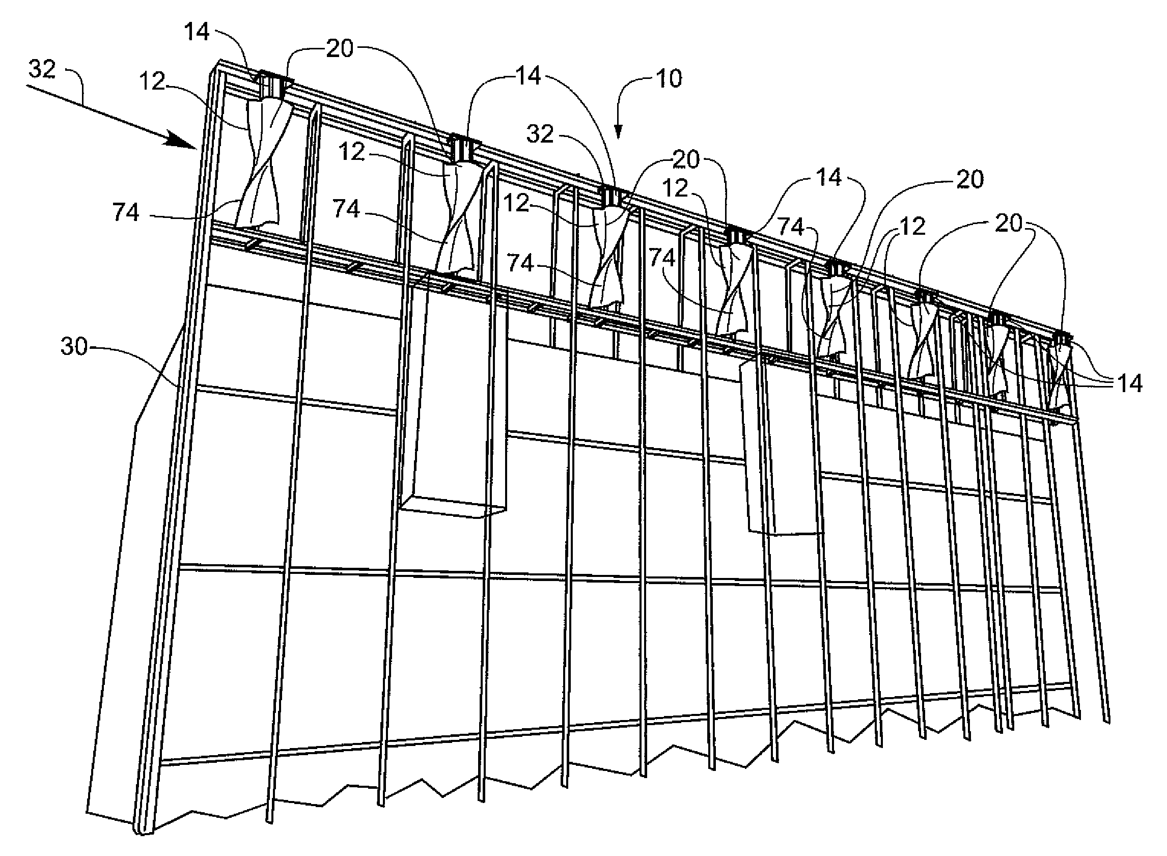
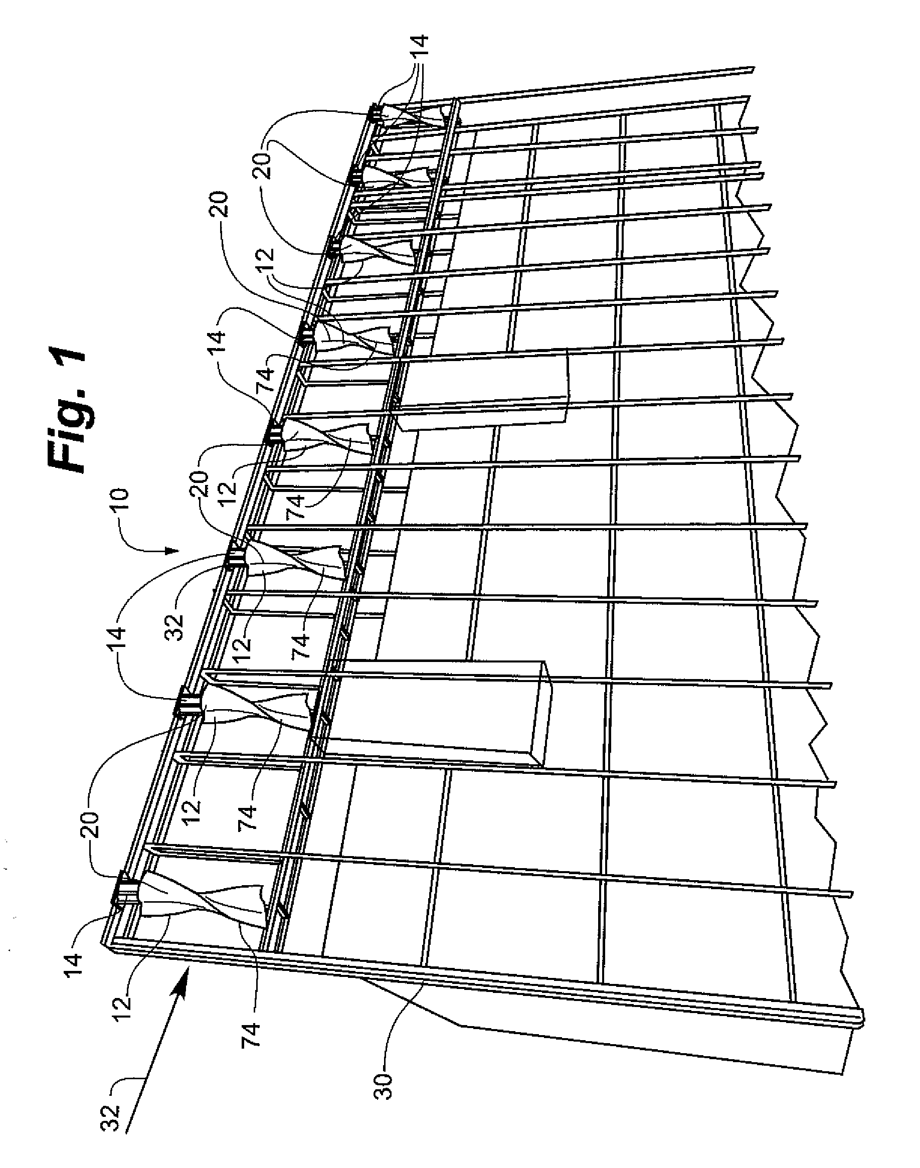
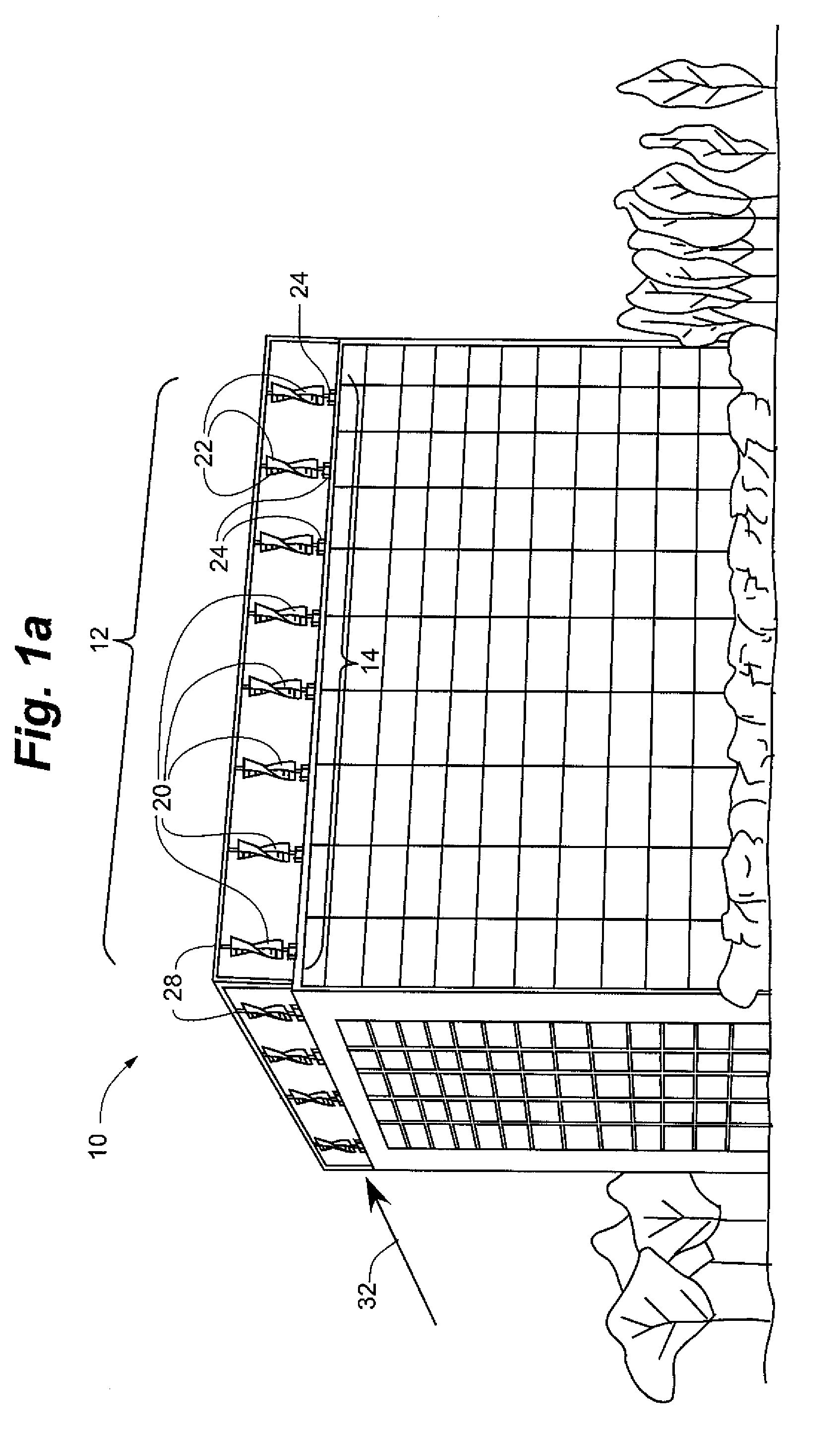
[0030]The linear power station of the present invention is shown generally at 10 in the figures. Each of the linear power stations 10, depicted generally in FIGS. 1 and 1a, is comprised of a turbine array 12 and a generator array 14. The turbine array 12 preferably includes plurality of turbines 20. The generator array 14 preferably includes at least one generator 24 in rotational communication with the turbines 20 or a plurality of generators 24, each respective generator 24 being in rotational communication with a respective turbine 20. In an embodiment, the individual generators 24 comprising the generator array 14 are in electrical communication.

[0031]Referring to FIG. 2, the turbines 20 of this embodiment have two major subcomponents; blade portion 22 and generator 24. The blade portion 22 includes flighting 74, the flighting 74 including a plurality of flights 25 integrated into the blade portion 22 and preferably extending the full height d...


PUM


Abstract

A linear power station, includes a turbine array comprised of a plurality of turbines, the turbines for harnessing the power of a moving fluid and each respective turbine being rotatable about a fixed axis of rotation by fluid flow that is omnidirectional with respect to the turbine, and a generator array comprised of at least one generator, the at least one generator being operably coupled to the turbine array for being rotated by the respective plurality of turbines of the turbine array.
A method of producing electrical power is further included.

Description

RELATED APPLICATIONS[0001]The present application claims the benefit of U.S. Provisional Application No. 60 / 958,781, filed Jul. 7, 2007 and included herein in its entirety by reference.FIELD OF THE INVENTION[0002]The present invention relates to fluid operated turbines. More particularly, the present invention relates to a plurality of fluid operated turbines integrated into a linear power station, particularly a linear power station that is integrated with a humanly occupiable building structure.DESCRIPTION OF RELATED ART[0003]The fluid turbines described herein are described and claimed in Canadian Patent 1,236,030, issued May 3, 1988, having common ownership with the present application and incorporated herein in its entirety by reference. No claim of priority to such patent is made hereby.BACKGROUND OF THE INVENTION[0004]Known wind turbines typically have a rotatable central hub coupled to a plurality of radially mounted blades much like the propeller of a propeller driven aircr...

Claims


Application Information

Patent Timeline
IPC IPC(8): F03D9/00H02K7/18F03B13/10
CPCF03B17/062Y02E10/74F03D9/008F03D11/04F05B2240/213F05B2240/2212F05B2240/40F05B2240/911F05B2240/9113F05B2240/93F05B2250/25Y02B10/30Y02E10/28Y02E10/727Y02E10/728F03D3/02F03D13/20Y02E10/30F03D9/25F03D9/34Y02E10/20
Inventor JOUTSINIEMI, RISTO
Owner WINDSIDE AMERICA
Why Eureka
Try Eureka