Adjustable correction for a variety of ambient lighting conditions

a technology of ambient lighting and adjustment, which is applied in the direction of spectacles/goggles, instruments, spectacles/goggles, etc., can solve the problems of image imperfections and the inability to provide the necessary correction for changing the spherical aberration of the ey

Inactive Publication Date: 2009-01-15
PIXELOPTICS
View PDF2 Cites 83 Cited by
  • Summary
  • Abstract
  • Description
  • Claims
  • Application Information

AI Technical Summary

Benefits of technology

[0015]In an embodiment of the invention, an ophthalmic lens has a sensor for detecting a change in ambient lighting and a controller. The controller adjusts an optical power of the ophthalmic lens based on the detected change in ambient lighting. The adjusted optical power of the ophthalmic lens substantially cancels a spherical aberration of an eye of a user of the ophthalmic lens.

Problems solved by technology

Spherical aberration is an optical error that typically results in image imperfections, such as halos.
Although a lens for correcting a fixed amount of spherical aberration is known, other problems arise.
While a conventional lens may correct for a fixed amount of spherical aberration, it cannot provide the necessary correction for changing spherical aberration in the eye.

Method used


Image

  • Adjustable correction for a variety of ambient lighting conditions
  • Adjustable correction for a variety of ambient lighting conditions
  • Adjustable correction for a variety of ambient lighting conditions

Examples


Embodiment Construction

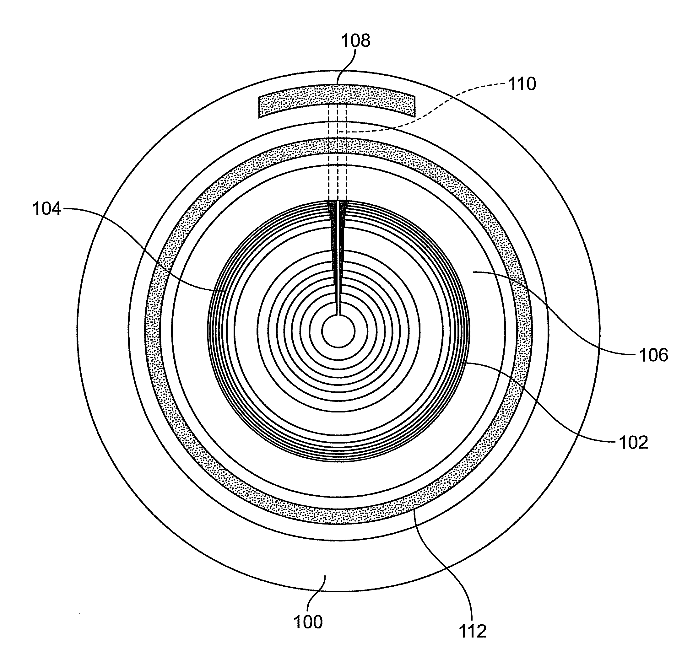
[0025]FIG. 6 shows a front view of a lens 100 having a sensor 106, a controller 108, and an electro-active region 102 with a plurality of concentric electrode rings 104 for correcting changing spherical aberration of an eye.

[0026]A lens system can include all of the components discussed herein, which can all be incorporated in a single lens, or alternatively, some of the components can be apart from the lens e.g., in a spectacle frame, a handheld device, or the user's apparel.

[0027]The sensor 106 senses a change in pupil size. In one approach, the sensor includes an imager in operative communication with a storage device and a processor. The imager is adapted for capturing images of the pupil over time. The images are typically stored in the storage device, although alternatively they may be sent directly as signals to the processor. The processor retrieves the images and compares contrast levels therebetween for identifying the dilation or constriction of the pupil over time. In an...


PUM


Abstract

A lens system is presented having a lens having an electro-active element, a sensor for sensing a change in ambient light, a controller in operative communication with the sensor, and a plurality of electrode rings electrically connected to the controller. The electrode rings may be concentric. The controller applies a voltage to the plurality of electrode rings when the sensor senses a change in ambient light. The application of voltage causes a change in the refractive index of the electro-active element for correcting a spherical aberration of the eye due to the sensed change in ambient light.

Description

CROSS REFERENCE TO RELATED APPLICATIONS[0001]This application claims priority from and incorporates by reference in its entirety the following provisional application:[0002]U.S. Ser. No. 60 / 929,041 filed on Jun. 8, 2007 and entitled “Ophthalmic Lens Having Adjustable Optical Power for a Variety of Ambient Lighting Conditions”.GOVERNMENT INTEREST STATEMENT[0003]This invention was made in whole or in part with government support under Contract Number FA7014-07-C-0013, awarded by the U.S. Air Force, Office of the Surgeon General (AF / SG). The government may have certain rights in the invention.BACKGROUND OF THE INVENTION[0004]A perfect lens focuses light to a single point on an optical axis of the lens. Spherical aberration is a deviation from the perfect focusing of light and occurs when light is focused to multiple points on the optical axis of the lens. Spherical aberration is an optical error that typically results in image imperfections, such as halos.[0005]Spherical aberration is ...

Claims


Application Information

Patent Timeline
Patent Type & Authority Applications(United States)
IPC IPC(8): G02C7/02
CPCG02C7/061G02C2202/22G02C7/083
Inventor BLUM, RONALD D.DUSTON, DWIGHT P.KOKONASKI, WILLIAMHADDOCK, JOSHUA N.VAN HEUGTEN, ANTHONY
Owner PIXELOPTICS
Why Eureka
Try Eureka