Self-priming electronic metering pump and priming methodology

a self-priming, electronic metering technology, applied in the direction of machines/engines, liquid fuel engines, positive displacement liquid engines, etc., can solve the problems of vapor lock, actual damage to the pump, and situation wear on the pump without any work

Inactive Publication Date: 2009-01-15
ADVANTAGE CONTROLS
View PDF17 Cites 23 Cited by
  • Summary
  • Abstract
  • Description
  • Claims
  • Application Information

AI Technical Summary

Benefits of technology

The patent text describes an electronic metering pump that uses a solenoid driven diaphragm to push liquid through guided checkballs. The pump also uses centrifugal force or displacement of a non-compressible liquid to effect pumping operations. The pump requires a constant supply of fluid to maintain its performance. A foot valve brings the liquid up through tubing out of a container and an injection valve delivers the liquid to the pressurized system. The pump works against back pressure and gravity and must be primed so that the liquid is up beyond the lower set of checkballs to begin delivery. This may be accomplished with a small manual valve at the rear of the pump head, with tubing returning to the container. Once priming is accomplished, the valve is shut off, and the liquid is forced up into the system during pumping. The technical effects of this patent text are to provide a detailed description of an electronic metering pump and its operation, and to ensure that the pump is always primed and ready for use.

Problems solved by technology

The technical problem addressed in this patent is the need for a pumping system that can detect when there is no fluid present in the pump and quickly initiate a priming operation to restore fluid flow. This is important for ensuring the pump operates efficiently and without the need for excessive wear and damage to the pumping mechanism.

Method used


Image

  • Self-priming electronic metering pump and priming methodology
  • Self-priming electronic metering pump and priming methodology
  • Self-priming electronic metering pump and priming methodology

Examples


Embodiment Construction

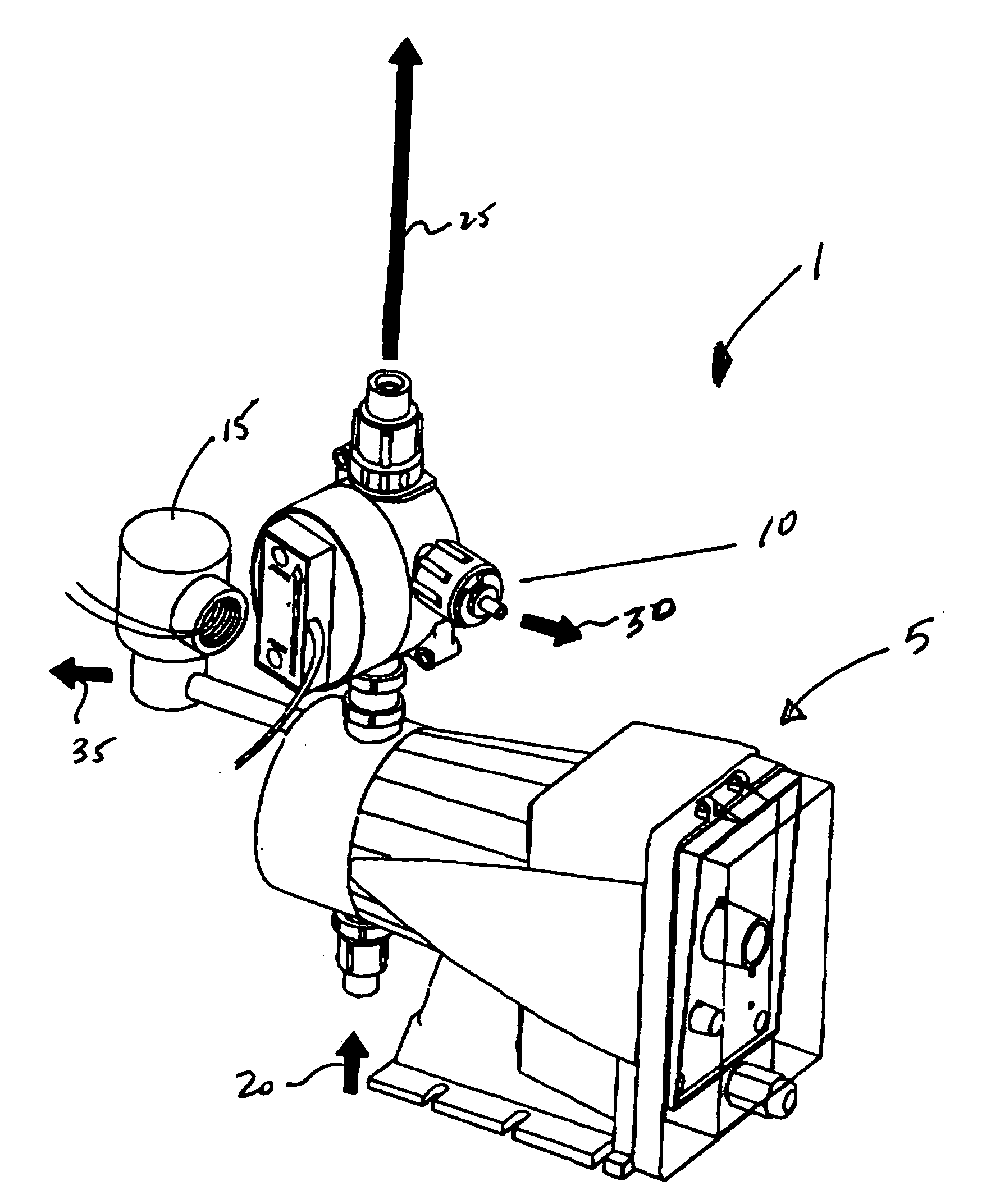
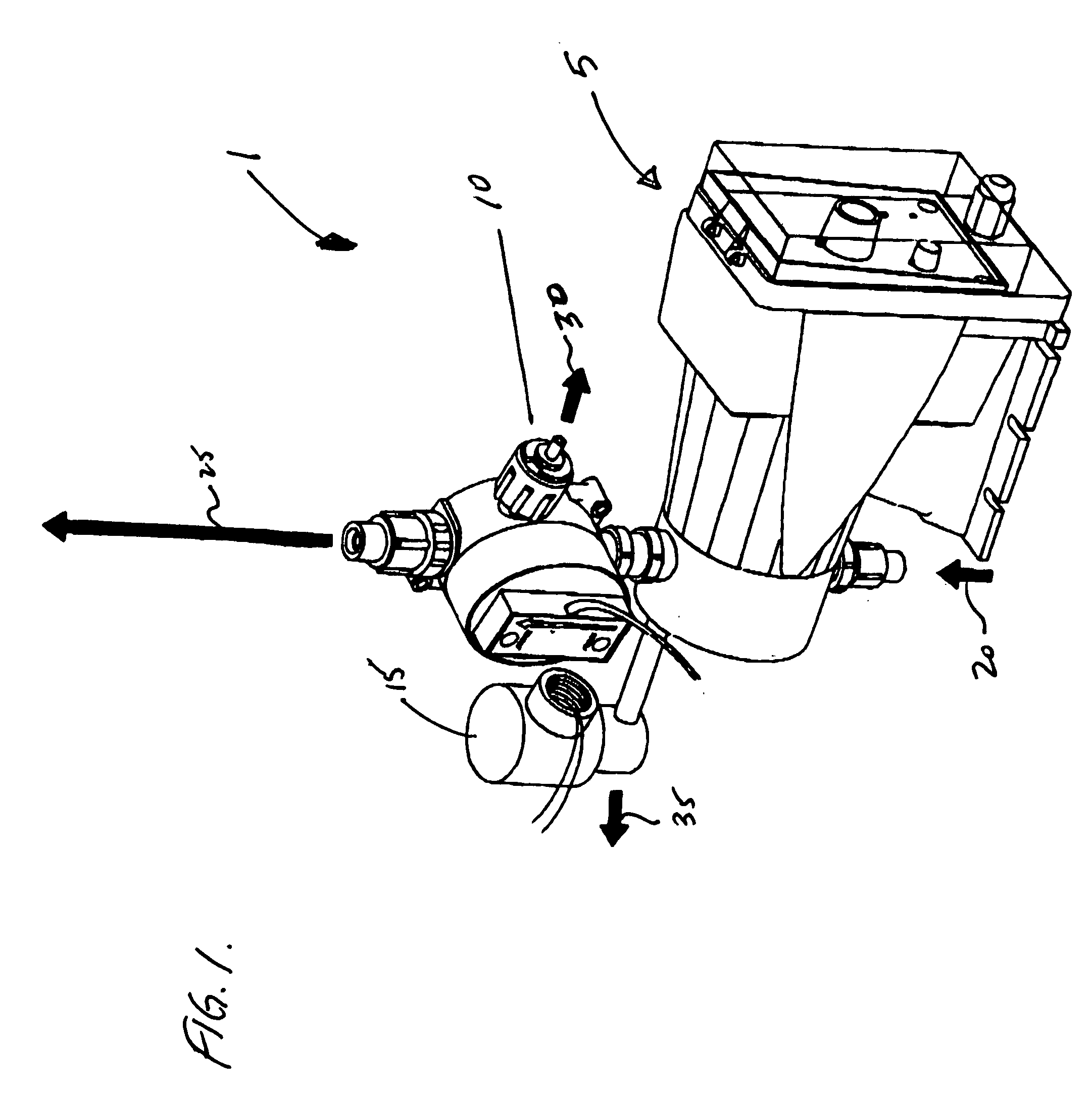
[0019]Referring now to FIG. 1, self priming pump assembly 1 is comprised of a electronic metering pump 5 of a conventional type. Examples of typical pumps are (1) LMI Milton Roy model AA15392SI; (2) Pulsafeeder model LE13Sa-PHC1; and Prominent model g / 4 . . . 0703. Pump 5 includes an electronic motor (not shown) which operates a displaceable element which creates a pressure differential within the pump. A flow sensor module 10 is affixed to pump 5 in fluid communication through a conduit. No specific geometry or arrangement of the fluid circuit is specified and the same is adapted to the particular physical and environmental needs of the application. A solenoid valve 15 is also engaged in fluid communication with pump 5 and / or flow sensor 10 to selectively provide an alternative fluid flow path upon the activation of solenoid valve 15 as part of the self priming functionality described more fully herein. Under normal operating conditions, pump inlet fluid flow 20 is drawn into pump ...


PUM


Abstract

An electronic metering pump system has a fluid flow detector for monitoring the output of the electronic metering pump to detect loss of prime. The fluid flow detector, upon detecting loss of fluid flow, initiates an electronic signal to a downstream solenoid valve which closes the output conduit of the electronic metering pump and facilitates the repriming of the pump and return of output fluid flow. The electronic signal may also be utilized to initiate an warning or alarm to an operator, either directly or by data network, that the system requires attention.

Description


Claims


Application Information

Patent Timeline
Owner ADVANTAGE CONTROLS
Why Eureka
Try Eureka