Waterproof Connector

a technology of connectors and connectors, applied in the direction of couplings/cases, coupling device connections, securing/insulating coupling contact members, etc., can solve the problems of losing sealing properties, becoming difficult to pull out a terminal from the waterproof connector, etc., to achieve the effect of suppressing the deformation amount of the terminal insertion opening, increasing the diameter and increasing the rigidity of the protruding portion

Active Publication Date: 2009-01-15
YAZAKI CORP
View PDF2 Cites 14 Cited by
  • Summary
  • Abstract
  • Description
  • Claims
  • Application Information

AI Technical Summary

Benefits of technology

[0012]In accordance with the waterproof connector of the present invention, the wire tube has the protruding portion protruding rearward from the terminal insertion opening of the mat seal. Accordingly, even if the electric wire in the rear of the rear grid is bent, a rear side end portion of the wire tube will be thrust against the rear grid, and a situation can be prevented, where the rear side end portion is thrust against the mat seal, and the terminal insertion opening of the mat seal 7 is deformed largely. Moreover, the rear side end portion of the wire tube is prevented from being thrust against the mat seal, and accordingly, the rear side end portion is prevented from digging thereinto, and a situation where such an end portion is caught on the rear grid at the time of pulling out the terminal from the waterproof connector can be prevented. Hence, even if the electric wire is bent, sealing properties between the electric wire and the mat seal can be ensured, and it is prevented from becoming difficult to pull out the terminal, and further, the wire tube can be prevented from separating from the waterproof connector at the time of pulling out the terminal.
[0013]Moreover, the diameter of the protruding portion is increased more than the diameters of the other portions of the wire tube. Accordingly, the rigidity of the protruding portion is enhanced. In such a way, even if the electric wire in the rear of the rear grid is bent, the wire tube becomes less likely to be deformed, whereby a deformation amount of the terminal insertion opening can be suppressed. Moreover, since the diameter of the protruding portion is increased, the water can be further suppressed from entering the waterproof connector, whereby waterproof performance thereof can be enhanced.
[0014]Furthermore, the protruding portion is formed of the material having the higher rigidity than the other portions of the wire tube. Accordingly, even if the electric wire in the rear of the rear grid is bent, the wire tube becomes less likely to be deformed, whereby the deformation amount of the terminal insertion opening can be suppressed.
[0015]Still further, the protruding portion is formed of the material having the smaller friction coefficient than the other portions of the wire tube. Therefore, force of pulling out the terminal can be suppressed from becoming excessively large owing to friction between the protruding portion and the rear grid at the time of pulling out the terminal. In particular, in the case where the entirety of the wire tube is formed of a material having a small friction coefficient, the friction force between the wire tube and the mat seal is decreased, and a possibility that the wire tube may separate from the waterproof connector is increased; however, such a situation can be suppressed when only the protruding portion is formed of the material having the small friction coefficient.

Problems solved by technology

However, in the conventional waterproof connector, there has been a possibility to lose the sealing properties in a case where the electric wire is bent in the rear of the rear grid.
Moreover, in this case, there have been possibilities that it may become difficult to pull out a terminal from the waterproof connector, and that the wire tube may separate therefrom at the time of pulling out the terminal.

Method used


Image

  • Waterproof Connector
  • Waterproof Connector
  • Waterproof Connector

Examples


Embodiment Construction

[0027]A description will be made of a preferred embodiment of the present invention based on the drawings.

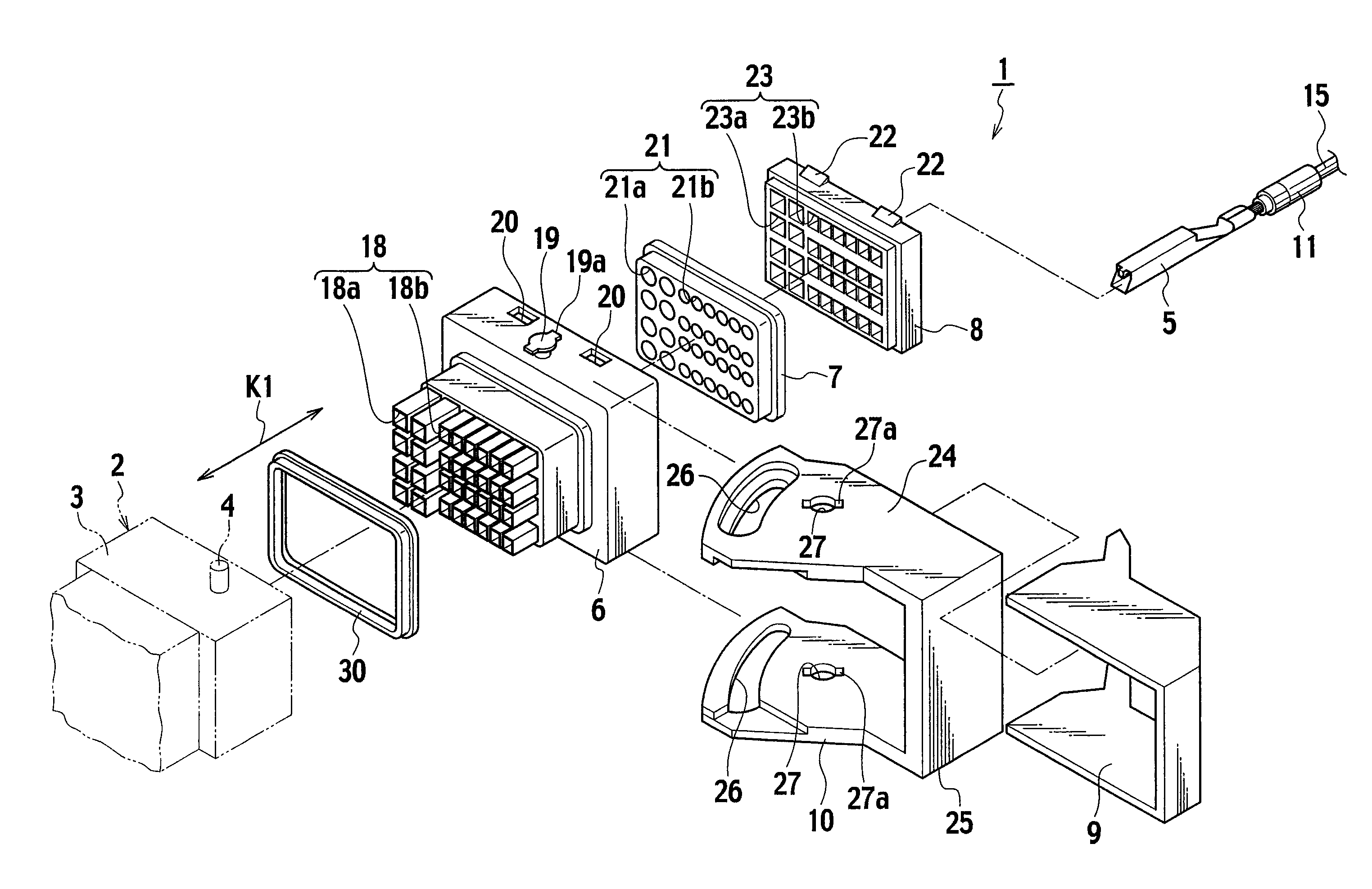
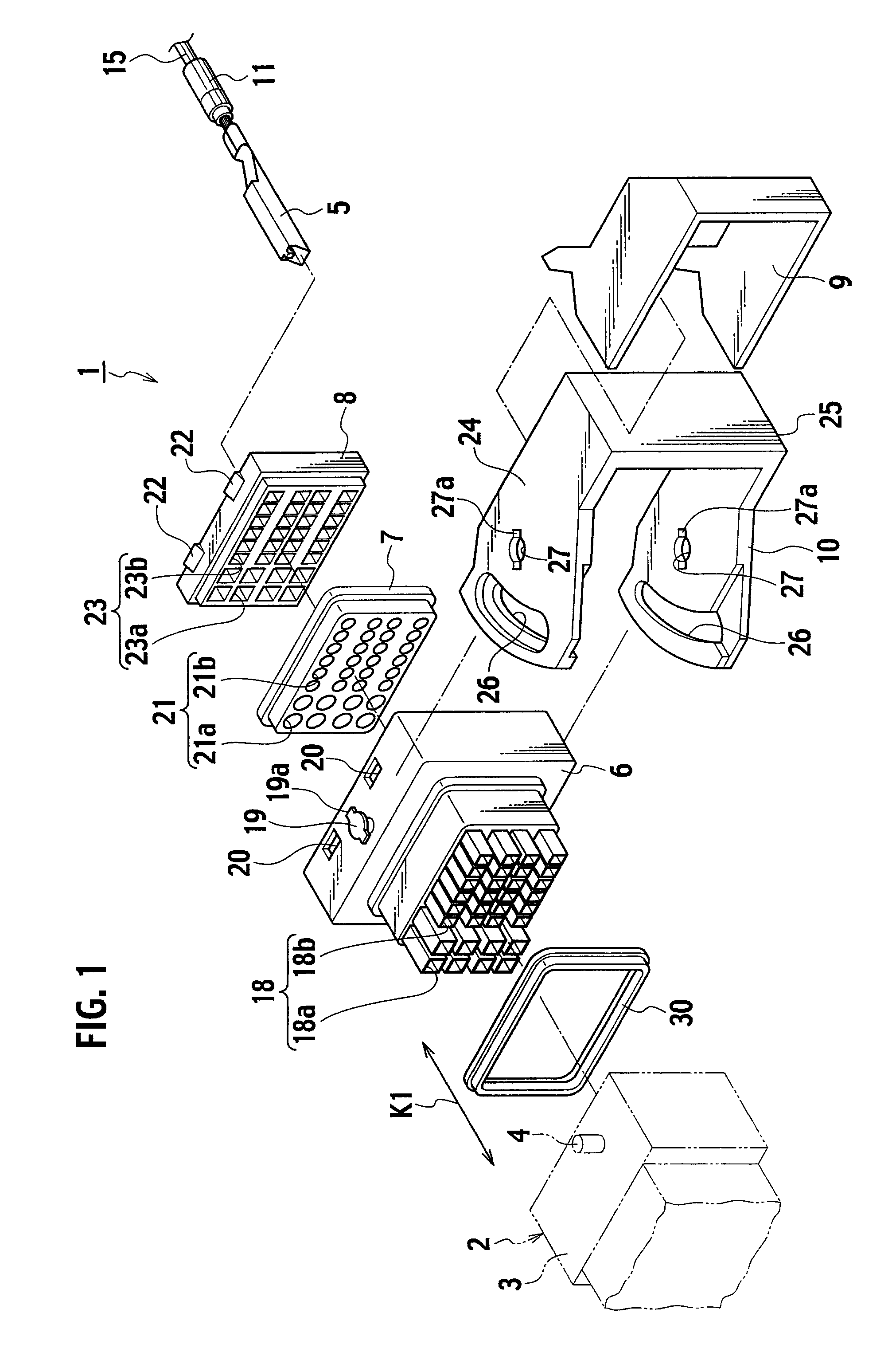
[0028]As shown in FIG. 1, a waterproof connector 1 is composed so as to be fitted and electrically connected to corresponding connector 2 (shown by chain double-dashed lines in FIG. 1).

[0029]The corresponding connector 2 includes: male-type terminal fittings (not shown, hereinafter referred to as male terminals); and a connector housing 3. Each of the male terminals is made of a conductive plate, and is crimped to a core wire of an electric wire.

[0030]The corresponding connector housing 3 is made of insulating synthetic resin and is formed into a tubular shape. The connector housing 3 has terminal receiving chambers which receive the male terminals. Moreover, protruding pins 4 are provided on the connector housing 3. Each of the protruding pin 4 protrudes outward of the connector housing 3 from an outer wall of the connector housing 3.

[0031]As shown in FIG. 1, the waterproof con...


PUM


Abstract

In a waterproof connector, a mat seal and a rear grid are attached to a rear side of a connector housing. These mat seal and rear grid include terminal insertion openings and electric wire insertion openings, respectively, which communicate with terminal receiving chambers. Wire tubes are fitted to electric wires to which large female terminals are crimped, and are brought into elastically intimate contact with inner walls of large terminal insertion openings of the mat seal. Moreover, each of the wire tubes includes a protruding portion that protrudes rearward from the large terminal insertion opening of the mat seal and is located in the large electric wire insertion opening.

Description

CROSS REFERENCE TO RELATED APPLICATION[0001]This application is based upon and claims the benefit of priority from Japanese Patent Application No. 2007-183597 filed on Jul. 12, 2007, the entire contents of which are incorporated herein by reference.BACKGROUND OF THE INVENTION[0002]1. Field of the Invention[0003]The present invention relates to a waterproof connector.[0004]2. Description of the Related Art[0005]In a conventional water proof connector, it is known to use a wire tube in order to ensure sealing properties between each of electric wires and a mat seal. In this conventional waterproof connector, the mat seal and a rear grid are mounted on a rear side (when viewed from a corresponding connector) of a housing in this order. The electric wire is inserted into the wire tube with a substantially cylindrical shape. The electric wire inserted into the wire tube is inserted into a terminal receiving chamber of the housing through a terminal insertion opening of the rear grid and ...

Claims


Application Information

Patent Timeline
Patent Type & Authority Applications(United States)
IPC IPC(8): H01R13/52
CPCH01R13/62938H01R13/5208
Inventor YONEDA, TAKAHIROSAWADA, RYOFUKUI, MASAYUKIKOIZUMI, MIKI
Owner YAZAKI CORP
Why Eureka
Try Eureka