
Footwear sole construction

a sole construction and shoe technology, applied in the field of shoe sole construction, can solve the problems of different problems, premature foot fatigue, and inability to provide firm support, and achieve the effect of effective and durable sole construction and easy tuning

Inactive Publication Date: 2009-01-22
WOLVERINE WORLD WIDE
View PDF45 Cites 66 Cited by
  • Summary
  • Abstract
  • Description
  • Claims
  • Application Information

AI Technical Summary

Benefits of technology

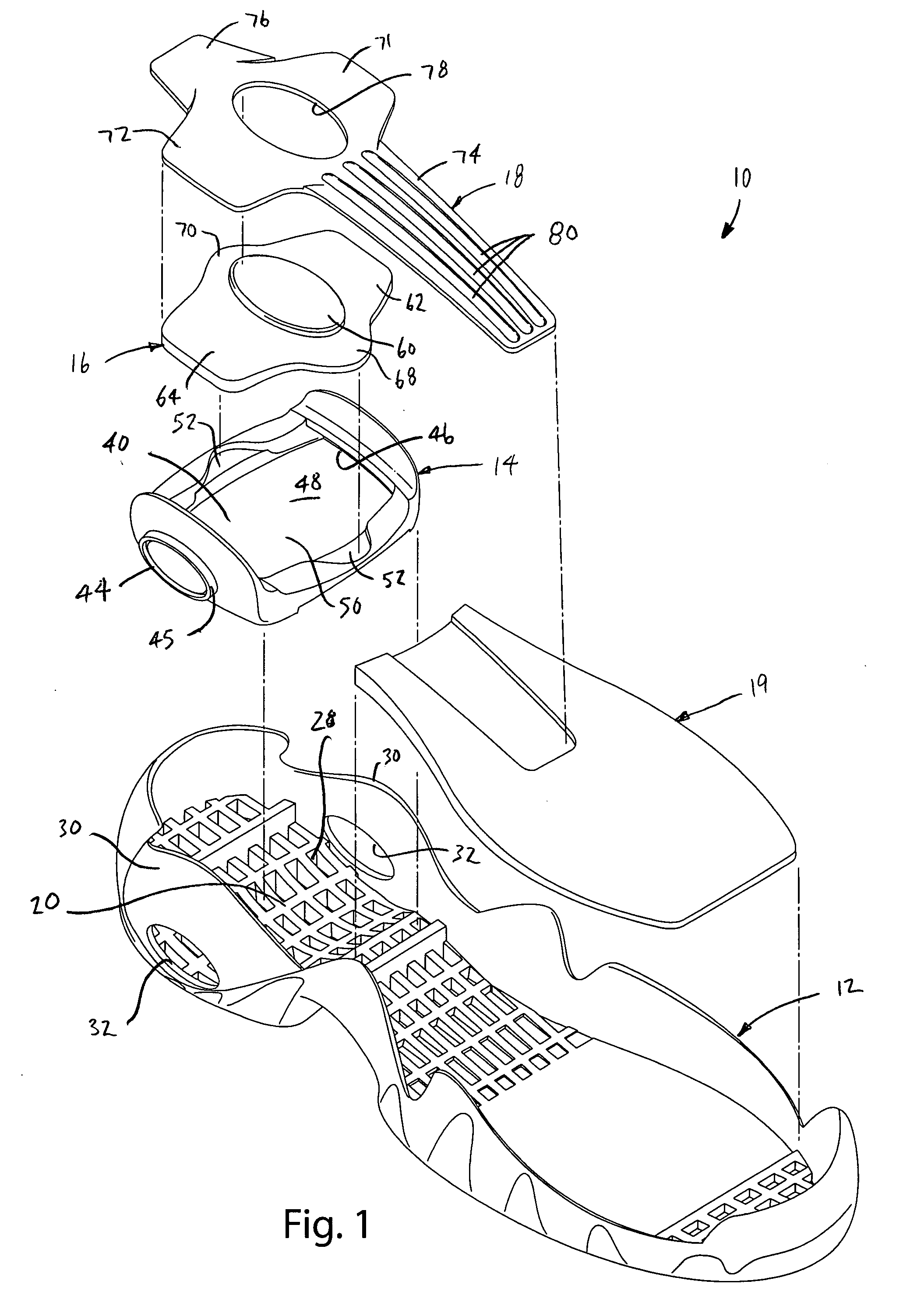
[0006]In one embodiment, the support element includes a forward extension that extends into the arch region to function as a shank. In one embodiment, the support element includes a rear extension that may assist in providing longitudinal alignment of the support element and may also provide supplemental heel support.
[0008]The present invention provides an effective and durable sole construction that provides graduated cushioning through a broad range of loads. The heel pad and support element may bend in a spring-like manner to absorb loads. Once the heel pad and support element have bent to a point where they bottom-out in the heel carrier, the components compress under further load, thereby providing a graduated response to loads. The support element may be used to provide supplemental cushioning and to maintain the heel pad in proper alignment with the heel carrier. When present, the central opening in the support element provides a soft region that helps to center the heel. The cushioning characteristics of the sole construction can be easily tuned through variations in the shape and materials of the sole construction components.

Problems solved by technology

The objectives of providing comfortable cushioning and firm support are often at odds.
An overly soft sole may not provide sufficient foot support and may lead to premature foot fatigue.
On the other hand, an overly stiff sole may lead to a different set of problems.
For example, an overly firm sole may feel uncomfortable and may not provide the cushioning needed to protect the wearer against the damage associated with repeated ground impact.

Method used


Image

  • Footwear sole construction
  • Footwear sole construction
  • Footwear sole construction

Examples


Embodiment Construction

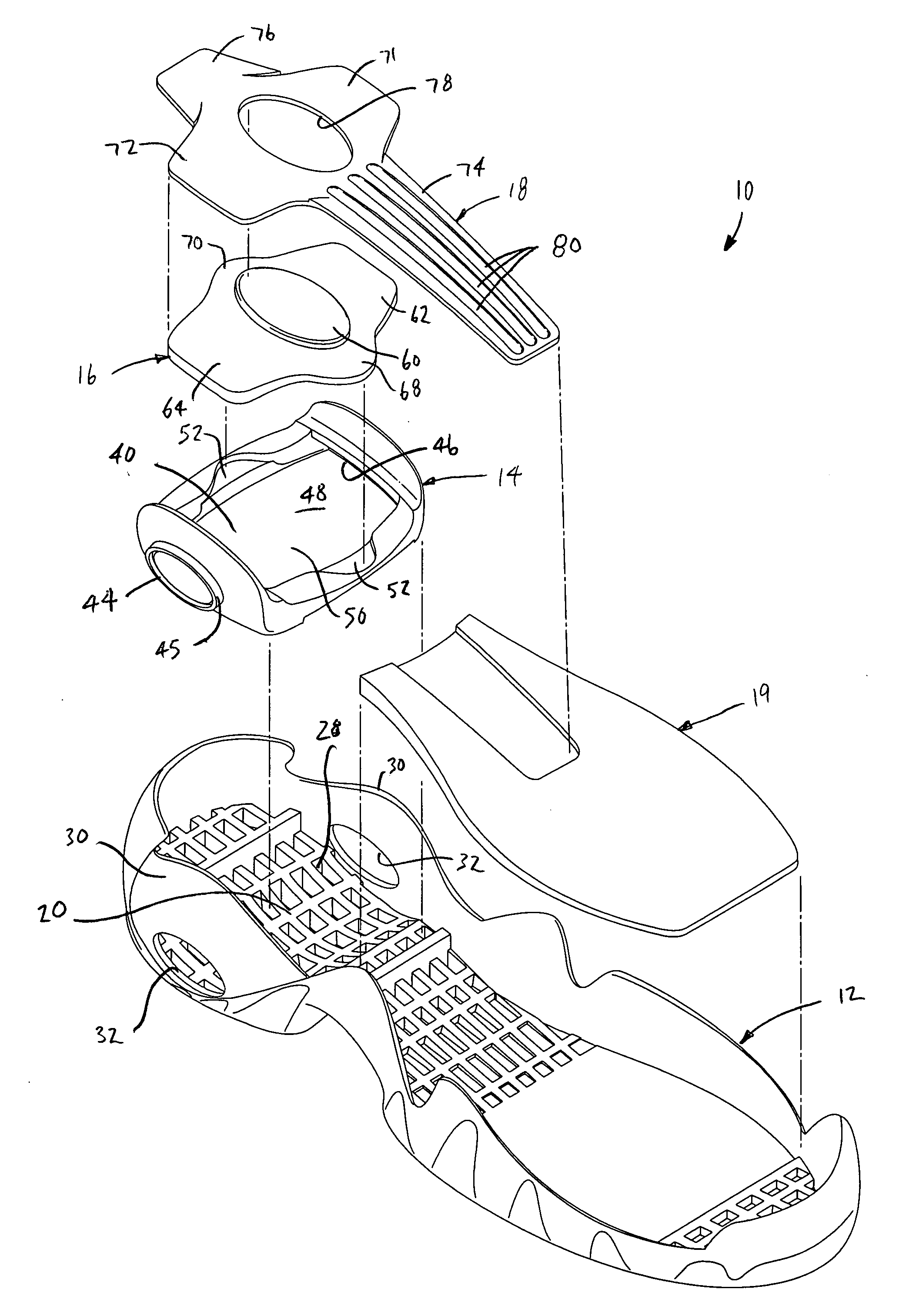
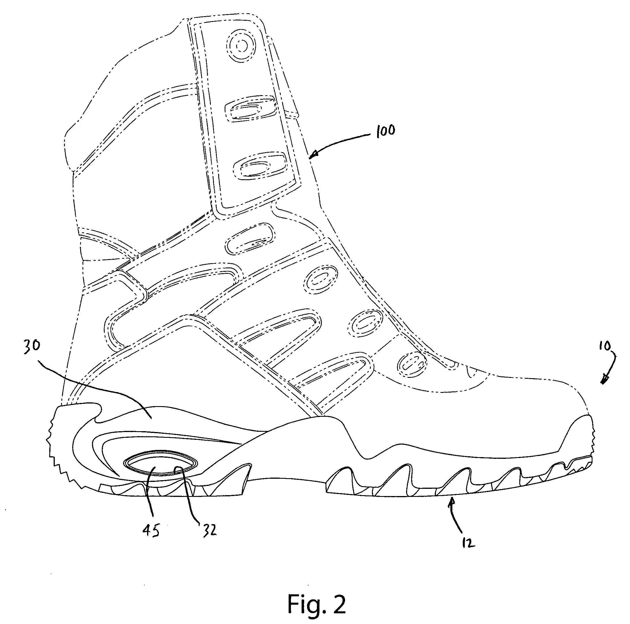
[0024]A sole construction manufactured in accordance with an embodiment of the present invention is shown in FIG. 1 and generally designated 10. In the illustrated embodiment, the sole construction 10 generally includes an outsole 12, a heel carrier 14, a heel pad 16 and a support element 18. The heel carrier 14 is interfitted with the outsole 12 and provides a cradle for the heel pad 16 and the support element 18. The heel pad 16 is fitted into the carrier 14 and is held by the carrier 14 in an upwardly bowed configuration. Accordingly, the heel pad 16 responds to heel load in part by flexing downwardly in a spring-like manner. The support element 18 overlies the heel pad 16 and, like the heel pad 16, may be fitted into the carrier 14 in an upwardly bowed configuration so that the support element 18 and heel pad 16 form a cooperative spring-like response to heel loads.

[0025]The sole construction of the present invention may be incorporated into essentially any type of footwear, suc...


PUM

PropertyMeasurementUnit
Lengthaaaaaaaaaa
Forceaaaaaaaaaa
Dimensionaaaaaaaaaa

Abstract

A sole construction having a heel carrier and an upwardly-arched heel pad. The heel pad is fitted into and supported by the heel carrier so that the heel pad provides a spring-like bending reaction to a load. The sole construction may further include a support element disposed above the heel pad and fitted into heel carrier. The support element may be upwardly-arching so that, like the heel pad, it provides spring-like bending reaction in response to a load. The support element and heel pad may be integrally formed, for example, by molding the heel pad directly onto the support element. The heel pad and / or support element may be fitted into slots in the lateral and medial sidewalls of the heel carrier to interconnect the heel pad, support element and heel carrier. The support element may have a forward extension to function as a shank.

Description

BACKGROUND OF THE INVENTION[0001]The present invention relates to footwear and more particularly to a sole construction for an article of footwear.[0002]The primary functional purposes of footwear are to protect and support the wearer's foot. Most of the support and protection afforded by an article of footwear is attributable to the design and configuration of the sole. The sole protects the foot in part by dispersing the force of sharp and pointed objects, such as rocks and sticks. The sole also provides cushioning that absorbs impact and protects the wearer (e.g. feet, ankles and knees) from the associated stress. As the same time, the foot has a natural shape and the sole plays a role in helping to support the foot in its proper shape to reduce the risk of the foot becoming fatigued over time.[0003]The objectives of providing comfortable cushioning and firm support are often at odds. Accordingly, there is an ongoing interest in developing footwear sole constructions that provide...

Claims


Application Information

Patent Timeline
IPC IPC(8): A43B7/00A43B13/28A43B13/42A43B21/00
CPCA43B7/14A43B13/12A43B23/22A43B13/183A43B21/26A43B13/14
Inventor NAKANO, KIYOTAKAREED, KARL A.SLATTERY, JOHN M.
Owner WOLVERINE WORLD WIDE
Learn More