Apparatus, system, and method for determining a time-temperature history of an aftertreatment device

Active Publication Date: 2009-01-22
CUMMINS FILTRATION IP INC
View PDF4 Cites 13 Cited by
  • Summary
  • Abstract
  • Description
  • Claims
  • Application Information

AI Technical Summary

Benefits of technology

[0017]Furthermore, the described features, advantages, and characteristics of the invention may be combined in any suitable manner in one or more embodiments. One skilled in the relevant art will recognize that the invention may be practiced without one or more of the specific features or advantages of a particular embodiment. In other instances, addi

Problems solved by technology

The thermal cycles may be intentional, for example during the removal of soot from a particulate filter, or unintentional such as when the engine experiences large changes in the required workload for the engine.
As the aftertreatment devices experience thermal cycles, the physical characteristics of the device can degrade over time.
For example, stresses on the substrate of the device experience wear and thermal fatigue, while catalytic aspects of the device may experience thermal degradation and deactivation.
The combination of time and temperature experienced by the aftertreatment device is particularly difficult to detect.
There are no direct measurements routinely used in real-time for applications to detect temperatures within an aftertreatment device.
The internal temperatures of the device are the most significant in terms of degradation, and the most difficult in terms of measuring.
Even when an aftertreatment device removed from an application for service and can be observed directly, there are no current techniques to estimate the time-temperature history of the device.
However, excessive device de

Method used


Image

  • Apparatus, system, and method for determining a time-temperature history of an aftertreatment device
  • Apparatus, system, and method for determining a time-temperature history of an aftertreatment device
  • Apparatus, system, and method for determining a time-temperature history of an aftertreatment device

Examples


Embodiment Construction

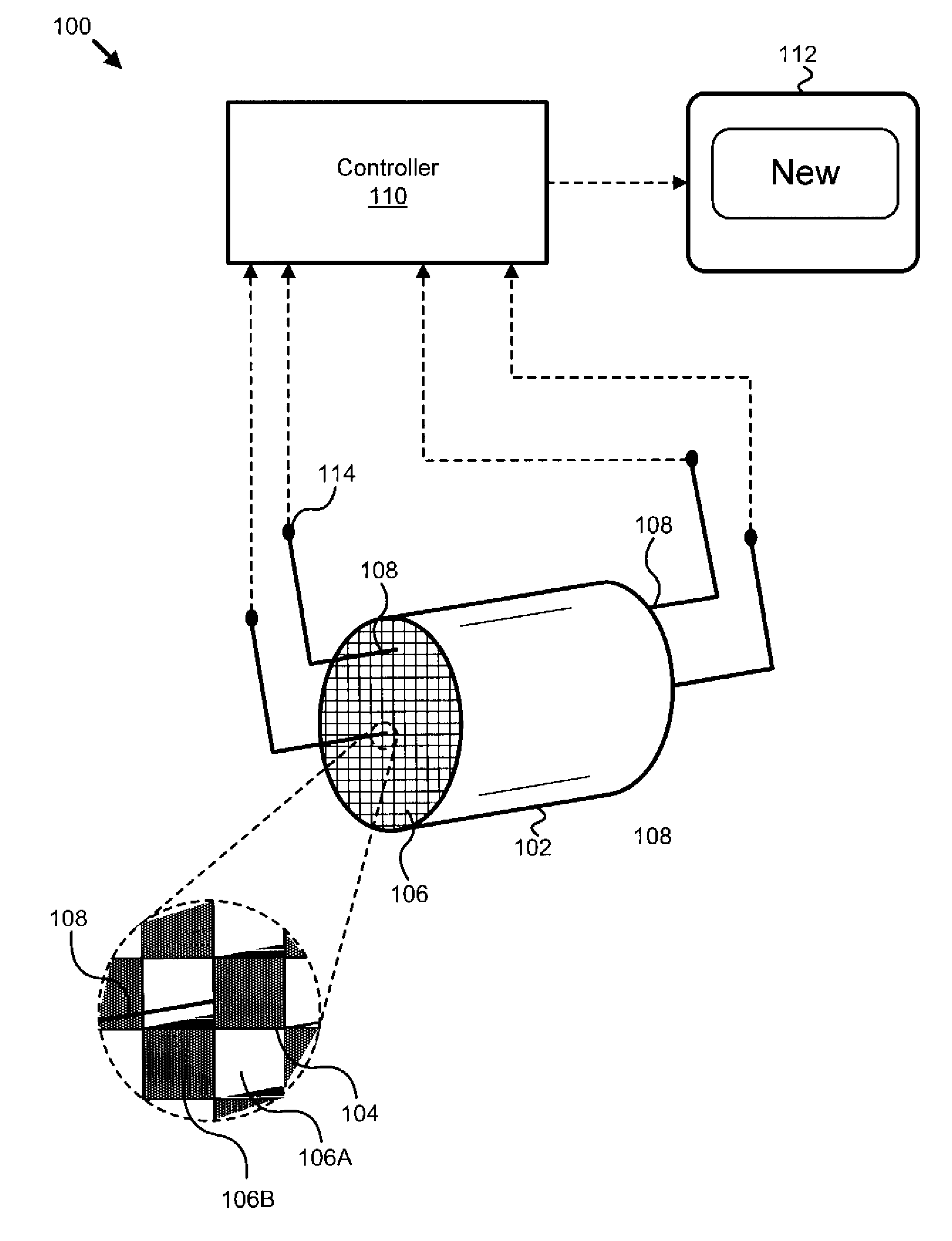
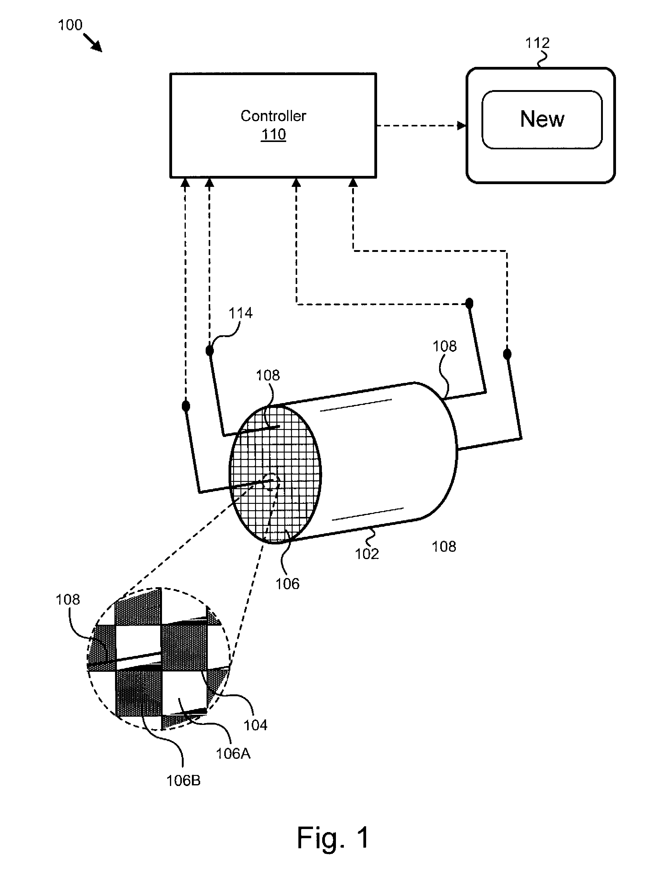
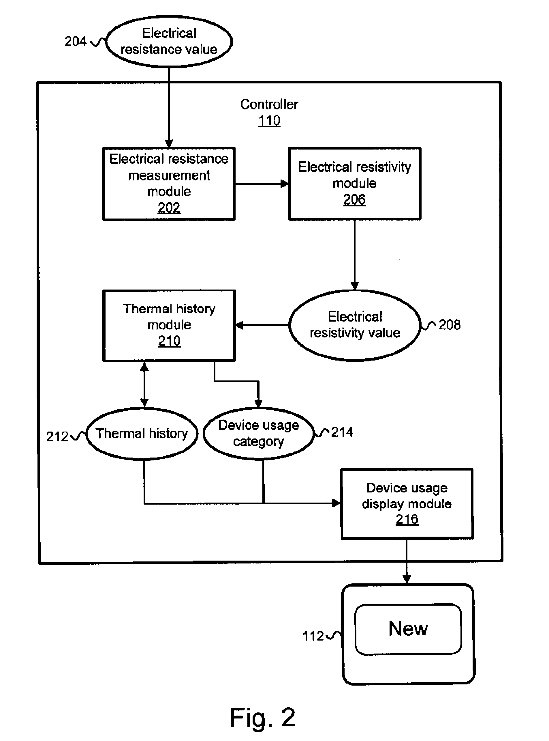
[0030]It will be readily understood that the components of the present invention, as generally described and illustrated in the figures herein, may be arranged and designed in a wide variety of different configurations. Thus, the following more detailed description of the embodiments of the apparatus, system, and method of the present invention, as presented in FIGS. 1 through 10, is not intended to limit the scope of the invention, as claimed, but is merely representative of selected embodiments of the invention.

[0031]Reference throughout this specification to “one embodiment” or “an embodiment” means that a particular feature, structure, or characteristic described in connection with the embodiment is included in at least one embodiment of the present invention. Thus, appearances of the phrases “in one embodiment” or “in an embodiment” in various places throughout this specification are not necessarily all referring to the same embodiment.

[0032]Furthermore, the described features,...


PUM


Abstract

An apparatus, system, and method are disclosed for determining a time-temperature history of an aftertreatment device. The apparatus includes an aftertreatment device comprising a substrate, and at least one thermal monitoring member (TMM) in thermal contact with the substrate. The TMMs may comprise a material that exhibits an electrical resistivity change at temperature over time. The apparatus may include a controller configured to measure the electrical resistivity of at least a portion of the TMMs, and to determine a thermal history based on the electrical resistivity measures.

Description

BACKGROUND OF THE INVENTION[0001]1. Field of the Invention[0002]This invention relates to aftertreatment devices for treating engine exhaust streams, and more particularly relates to determining the time-temperature experienced in aftertreatment devices.[0003]2. Description of the Related Art[0004]Emissions regulations for internal combustion engines have changed rapidly in recent years. To meet the new regulations, many engine manufacturers have had to install aftertreatment devices to reduce emissions in the exhaust gases, or to condition the exhaust gases to assist other aftertreatment devices. For example, particulate filters remove soot from the exhaust gases of a diesel engine, and diesel oxidation catalysts are sometimes used to generate temperature in the exhaust gas to assist a particulate filter in oxidizing the soot off of the filter.[0005]Most aftertreatment devices experience thermal cycles during the operations of the engine. The thermal cycles may be intentional, for ...

Claims


Application Information

Patent Timeline
IPC IPC(8): F01N3/10G01K3/04G06F19/00
CPCF01N3/021F01N11/002F01N2550/00F01N2560/06Y02T10/47G01K1/022G01K3/14G01K2205/04Y02T10/20F01N2560/12Y02T10/12Y02T10/40
Inventor YONUSHONIS, THOMAS M.STAFFORD, RANDALL J.SIMON, III, CONRAD J.BLACKWELL, BRYAN E.WESTERSON, KEVIN
Owner CUMMINS FILTRATION IP INC
Why Eureka
Try Eureka