Packaging Can and Method and Apparatus for Its Manufacture

a technology for packaging cans and cans, applied in the field of packaging cans for foodtuffs, can solve the problems of inherently slow process, long manufacturing time for manufacturing ring and fixing the lidding material to this ring, and substantial material waste, so as to reduce the incidence of wrinkles in the lidding material and facilitate the opening

Active Publication Date: 2009-01-22
CROWN PACKAGING TECH
View PDF12 Cites 14 Cited by
  • Summary
  • Abstract
  • Description
  • Claims
  • Application Information

AI Technical Summary

Benefits of technology

[0009]The lid may be fixed by tightly heat sealing for fusion of the lidding material directly onto the can body sidewall. This “sealing surface” may be substantially perpendicular to the plane of the access opening. In preferred embodiments of the invention, however, the sealing surface may be inclined at an angle so that opening of the closed container is not entirely in shear mode as would happen when the seam surface is vertical and the pull is vertical. By increasing the sealing surface angle, the container has been found to be easier to open without risking tearing off the tab, even if the customer pulls vertically.
[0010]A further advantage of the inclined sealing surface is that the incidence of wrinkles in the lidding material is reduced adjacent the can sidewall and localised peel from the can sidewall is eliminated.
[0024]Ideally, the punch has an end portion which extends axially at least 2 mm. This end portion carries the lidding material as it forms around the can body so that the diameter of the punch end portion needs to be an interference fit or only sufficiently less than the can body inner wall and the thickness of the lidding material that the cup shape formed by the lidding material is held for bonding against the can body sidewall without damaging the lidding material or base flange. The seal length may be greater than 2 mm, for example around 2.5 mm. The punch internal diameter may be slightly greater than the can internal diameter so as to stretch the can body in an interference fit to assist in providing pressure across the seal and create a good bond.

Problems solved by technology

However, the production of this ring leads to substantial wastage of material since the central part of the ring cannot economically be re-used for conventional can component sizes.
Manufacturing time using separate stages for manufacturing the ring and fixing the lidding material to this ring is also long.
This process is inherently slow because not only does the foil membrane require preforming but careful handling is needed for location in the can body.

Method used


Image

  • Packaging Can and Method and Apparatus for Its Manufacture
  • Packaging Can and Method and Apparatus for Its Manufacture
  • Packaging Can and Method and Apparatus for Its Manufacture

Examples


first embodiment

[0046]In the following figures, the elements analogous to those of the first embodiment are designated by identical references.

second embodiment

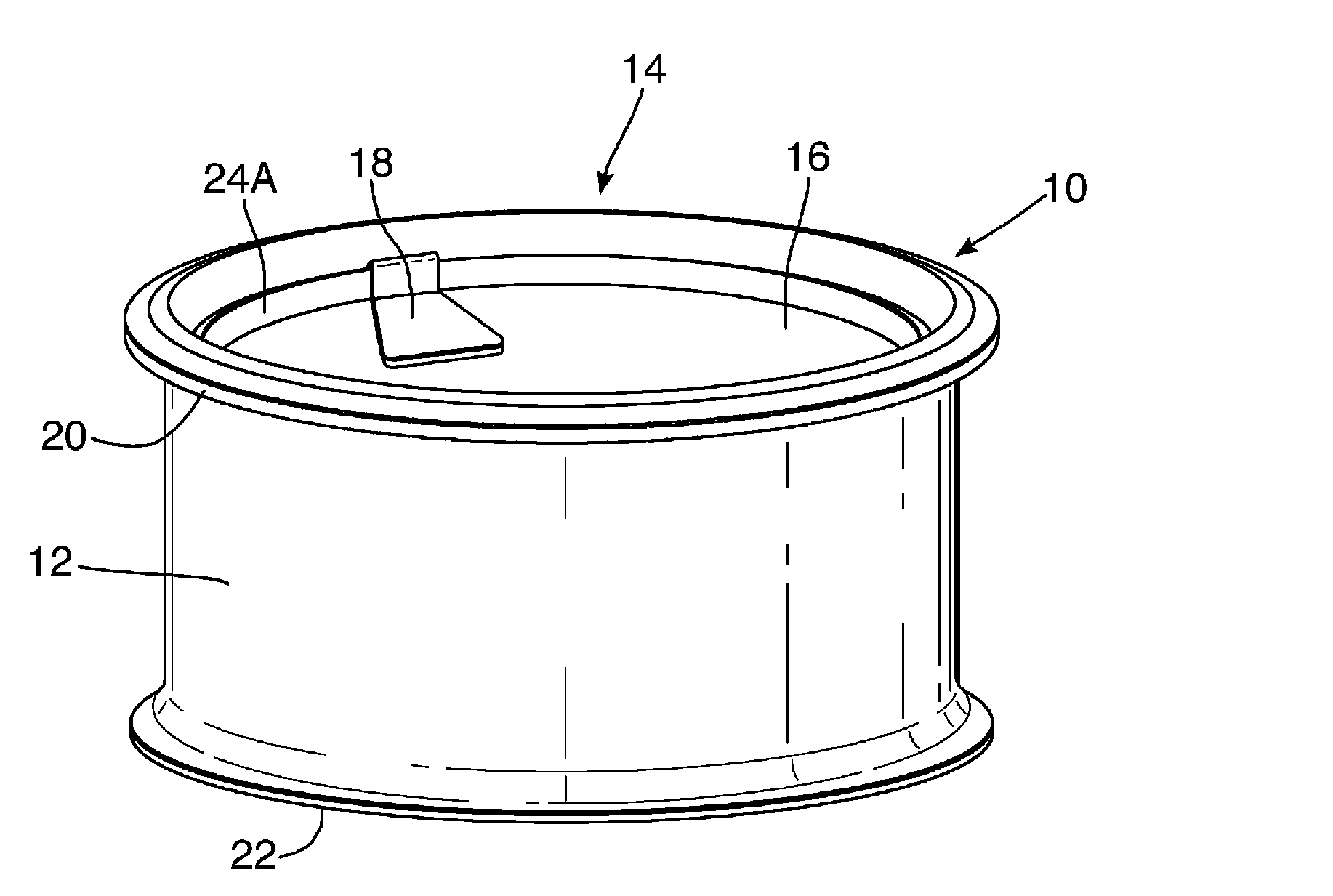
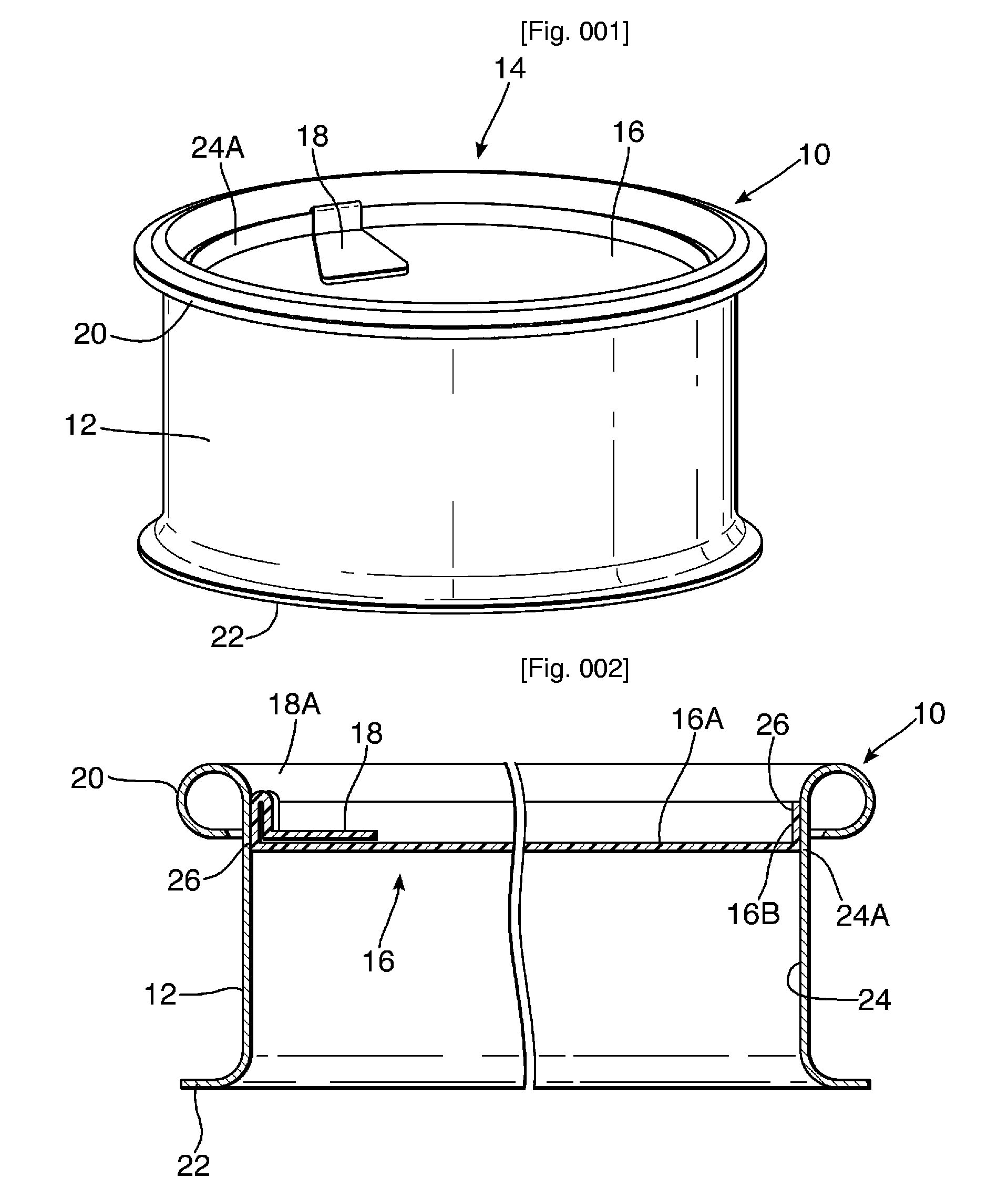
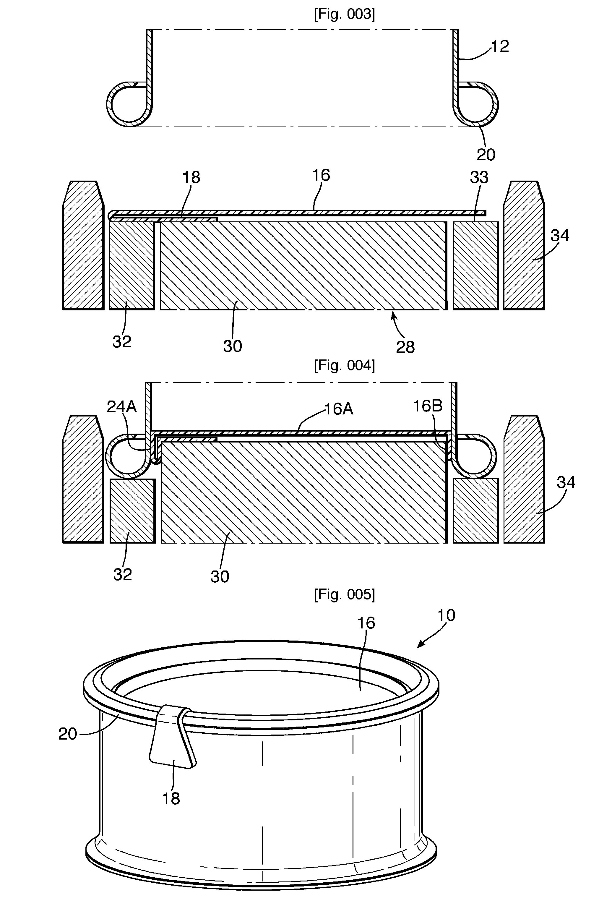
[0047]FIGS. 5 and 6 represent the invention. This embodiment differs from the previous one in that the tab 18 extends over the outside of the can body 12. The manufacturing process of this embodiment is represented in FIGS. 7 and 8. Unlike the process of FIGS. 3 and 4, the lid is centred on the support 28 with the tab folded back. During the stage of drawing the lid 16, the centring sleeve 34 allows the tab 18 to be guided in such a way that it extended along the can body 12.

third embodiment

[0048]FIG. 9 shows the invention, in which the sealing surface 24A is inclined at an angle of 45°. The tab in its folded and unfolded positions corresponds to that shown in FIGS. 1 and 5. The tab could be pre-folded and then the lidding material placed on the punch. Alternatively, the punch could be allowed to fold the tab, although care is then required to avoid the tab bonding to the top of the curl of the can body.

[0049]In a small scale trial, the embodiments of FIG. 2 (vertical seal) and FIG. 9 were tested by a random group for openability. The vertical sealing surface of the cans of FIG. 2 was considered by many of the group to be unconventional and so individuals had to decide on a new opening technique. Two separate sample batches of cans according to FIG. 2 were tested by the group. In the first batch, 61% of the tabs stayed attached and 31% of the ends were removed completely. In the second batch, only 17% of tabs stayed attached and 8% of the ends were removed completely. ...


PUM

PropertyMeasurementUnit
thicknessaaaaaaaaaa
angleaaaaaaaaaa
surface angleaaaaaaaaaa

Abstract

A can for packaging food, comprising a metal can body and a diaphragm lid (16) formed of lidding material which comprises a multilayer structure with at least an aluminium layer of from 6 to 90 microns thickness and a bond layer for fixing the lid (16) directly to the can body. One method for forming the can forms the lidding material by using an outwardly extending curl (20) at one end of the metal can body as the draw die. Lidding material which is carried by the body maker punch is drawn around the curl of the can body draw die so as to form the lidding material into a cup shape.

Description

TECHNICAL FIELD[0001]This invention relates to a can for packaging foodstuffs and a method and apparatus for forming such a can. The invention also relates to the forming of lidding materials for fixing to metal packaging such as metal cans.[0002]In particular, but not exclusively, it relates to the packaging of solid food, for people or pets. Such cans will also be referred to hereinafter as “food cans”.BACKGROUND ART[0003]Metal packaging is known in which a can body having a metal ring seamed to one end of the can body supports a peelable lid which comprises a multi-layer membrane having typically a peelable polypropylene layer, a layer of aluminium, and an outer layer of print, lacquer, PET or other coating. The material of the lidding material is generally chosen according to the requirements dictated by the product with which the can body is filled. For example, there is a need for maintaining seal integrity during processing, sterilisation etc. of food products but the lid mus...

Claims


Application Information

Patent Timeline
Patent Type & Authority Applications(United States)
IPC IPC(8): B65D85/00B65D1/40B21D51/28
CPCB21D51/2653B21D51/2661B21D51/10B65D2577/205
Inventor CAUNTER, NICHOLAS JAMESGLEDHILL, TANYA RUTHMAXWELL, IANRIVIERE, MAURICE
Owner CROWN PACKAGING TECH
Why Eureka
Try Eureka