Method for vertical positioning of dental implants

a technology for dental implants and vertical positioning, applied in the field of dental implants, can solve problems such as insufficient bone relief, and achieve the effects of improving the function and appearance of dental implants, ensuring the long-term survivability of implants, and improving the accuracy of surgical implant placemen

Inactive Publication Date: 2009-01-22
CARLTON DANA ALAN
View PDF9 Cites 0 Cited by
  • Summary
  • Abstract
  • Description
  • Claims
  • Application Information

AI Technical Summary

Benefits of technology

[0023]The invention is useful for improving the accuracy of surgical implant placement, thereby improving the function and appearance of dental implants. By reducing the frequency with which implants must be removed for vertical repositioning, the invention is useful for ensuring the long-term survivability of the implant. In particular, the invention is useful for ensuring that the implant will not have to be removed due to lack of engagement between the conical taper on the implant collar and the hole countersunk area. In addition, the invention is useful for ensuring that the hole is drilled to the proper depth before being tapped (if required) so that possible damage to the threads and bone during drilling is avoided. Furthermore, the invention is useful for ensuring a smooth emergence profile for the crown relative to the implant, and for avoiding an additional surgical procedure for removing bone around the margin of an implant to enable installation of an impression cap.
[0024]The method of the invention may be incorporated in a computer aided implant placement system to improve the precision and efficiency of at least some of the steps of the method, including hole drilling and countersinking, placement device insertion, gap inspection, hole depth estimation, and / or bone machining. This involves creating a virtual system in the computer for planning and guiding the surgical procedure, splint or stent manufacturing, and clinical implant placement. This approach ensures that the bone and soft tissue are properly prepared so that the implant margin is precisely and correctly positioned. The computerized implant positioning system may be used in both clinical and non-clinical laboratory applications.

Problems solved by technology

Lack of engagement of the impression cap on the fully inserted positioning device indicates inadequate relief of bone around the implant margin and the need for use of the extended countersink bur.

Method used


Image

  • Method for vertical positioning of dental implants
  • Method for vertical positioning of dental implants
  • Method for vertical positioning of dental implants

Examples


Embodiment Construction

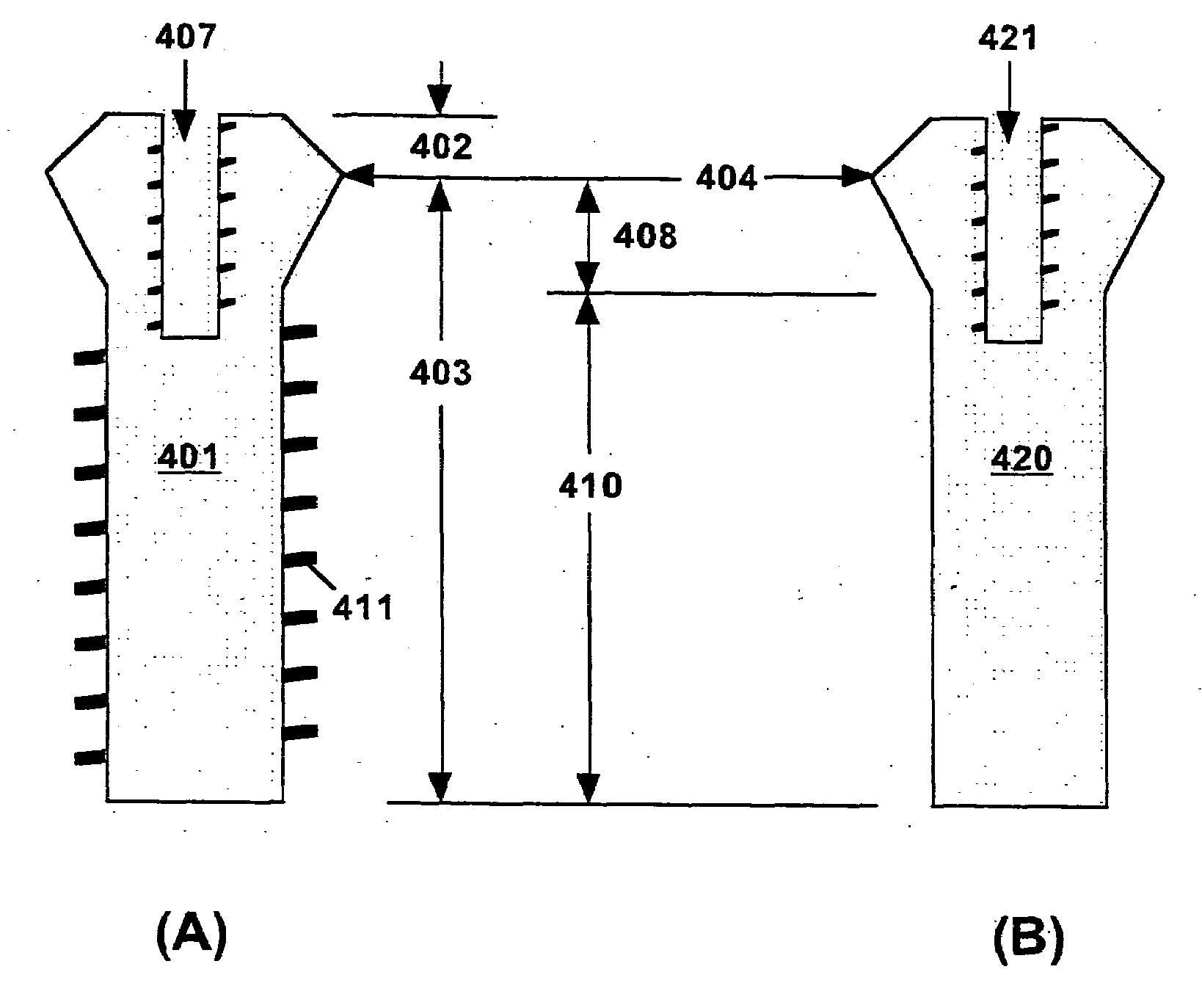
[0035]Technical terms used in this document are generally known to those skilled in the art. The term “vertical” denotes the direction along the axis of a hole in which a dental implant is inserted, wherein the “lower portion” of the implant (or implant positioning device) is located toward the bottom of the hole, and the “upper portion” of the implant (or implant positioning device) is located toward the top of the hole. The term “conical” is used in the general sense to denote a three-dimensional conical shape and encompasses both right circular cones and those for which an axial cross-section of the cone comprises a curved line. The term “conical” also encompasses implants with a conical emergence profile and a cylindrical top portion. As applied to the lower portion of an implant or implant positioning device, the term “cylindrical” also encompasses a lower portion tapered to have smaller diameter at the bottom.

[0036]The terminology used for an implant is the same whether the im...


PUM


Abstract

A positioning device is used to place an implant in the proper vertical position within the soft tissue and bone, provide space for subsequent procedures, and create a proper emergence profile for the final restoration. The lower portion of the positioning device has substantially the same outer shape as that of the implant but without external screw threads or other mechanical features for anchoring the implant in the jawbone. After the hole is countersunk, the depth of the hole in the jawbone is increased incrementally and checked with the positioning device for collar engagement and location of the margin within the gum tissue and bone. After the proper vertical position is attained, a special countersink bur may be used to create needed space around the implant margin and provide a proper crown emergence profile.

Description

[0001]This application is a divisional of U.S. patent application Ser. No. 11 / 476,987, filed Jun. 27, 2006.BACKGROUND OF THE INVENTION[0002]1. Field of the Invention[0003]This invention is concerned with dentistry, and in particular with a method for vertical positioning of dental implants.[0004]2. Description of the Related Art[0005]Dental implants are used in the practice of dentistry to replace teeth that have become unserviceable and / or painful to the patient due to disease or physical damage. A tooth implant basically comprises a metallic implant part, a metallic abutment, and a crown. The implant part typically has a threaded cylindrical bottom portion that is screwed into a drilled and tapped hole in the jawbone, and a conically tapered top portion that preferably extends to below the outer surface of the gum tissue. For some implant parts, the cylindrical lower portion is tapered, being slightly smaller in diameter at the bottom. The abutment typically comprises a tapered po...

Claims


Application Information

Patent Timeline
Patent Type & Authority Applications(United States)
IPC IPC(8): A61C8/00
CPCA61C8/0089
Inventor CARLTON, DANA ALAN
Owner CARLTON DANA ALAN
Why Eureka
Try Eureka