Measuring device and accessories for preparing quilt pieces

Active Publication Date: 2009-01-29
BRADY JOHN R
View PDF54 Cites 28 Cited by
  • Summary
  • Abstract
  • Description
  • Claims
  • Application Information

AI Technical Summary

Benefits of technology

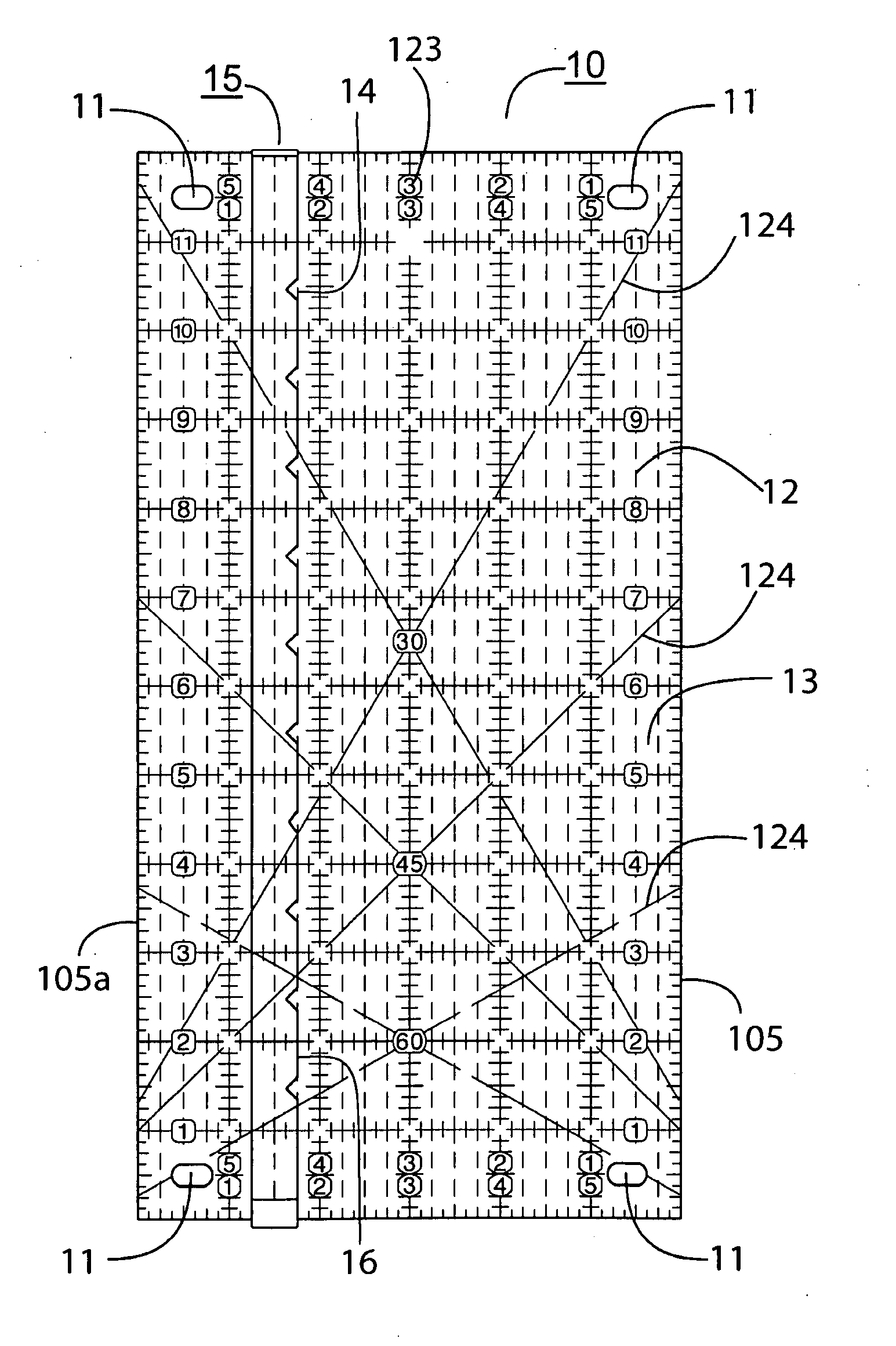
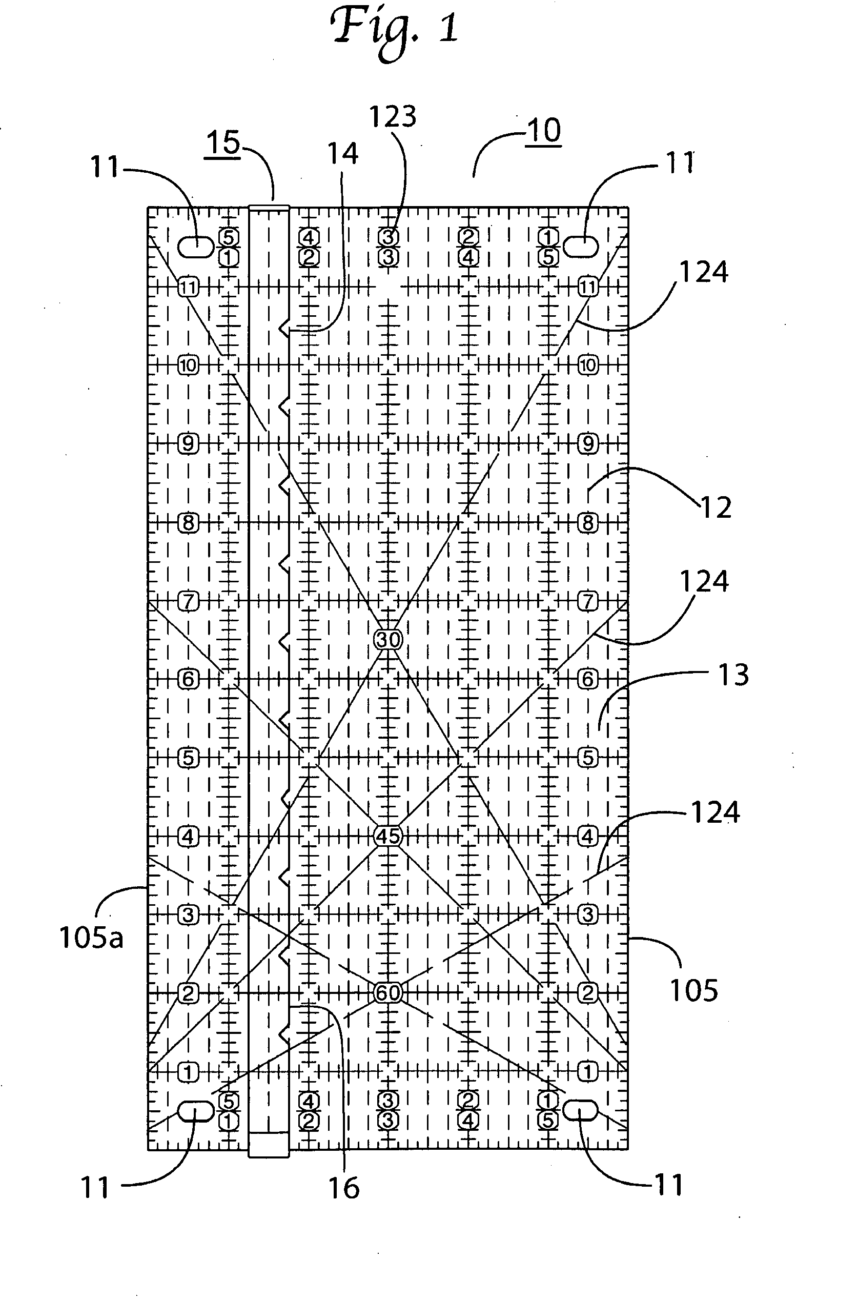
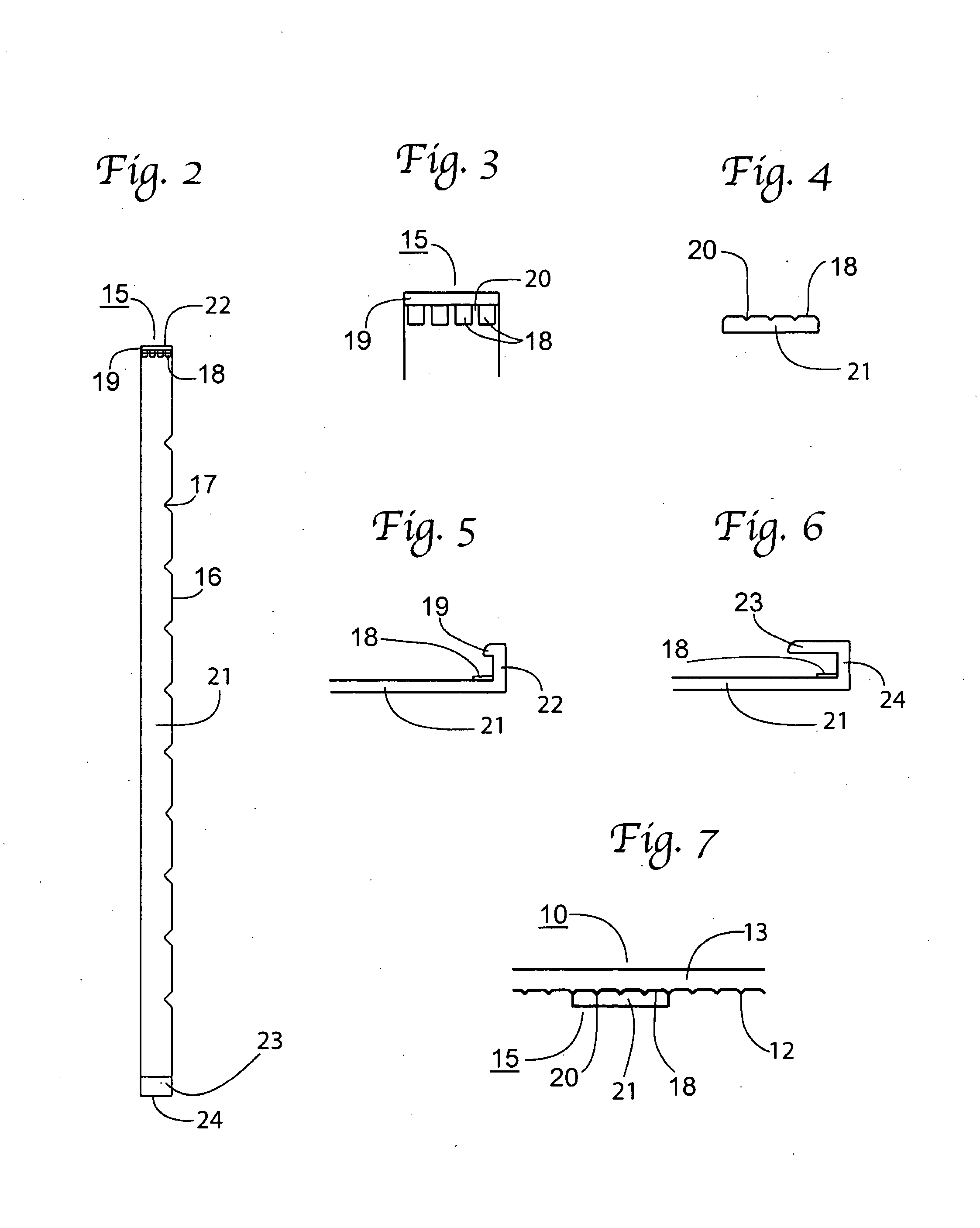
[0039]In one embodiment, a transparent measuring apparatus for material is presented. The apparatus includes a planar structure including a top surface, bottom surface, a left edge, a right edge, a top end, a bottom end and at least one hole for attachment of accessories. A plurality of measurement lines is formed on at least one of the top and bottom surfaces. A material alignment guide is removably attached to the bottom surface. The material alignment guide includes a first edge for aligning the material and is configured for moveably aligning the first edge with the measurement lines. Protrusions extend below the bottom surface and adjacent to the left and right edges. The protrusions extend a sufficient distance from the bottom surface to facilitate movement of the material alignment device when the protrusions are placed on a flat surface. At least one first accessory is attachable to the planer structure wherein the first accessory adds width to the planer structure. At least a second accessory is attachable to the planer structure wherein the second accessory adds length to the planer structure. At least a third accessory is attachable to the planer structure wherein the third accessory provides a safety barrier when cutting along an edge of the planer structure. At least a fourth accessory is attachable to the planer structure wherein the fourth accessory provides a slot for guiding cutting along an edge of the planer structure. In another embodiment the material alignment guide includes an elongate strip and the first edge includes notches for viewing a proper alignment of the material with the first edge. In another embodiment the plurality of measurement lines includes raised ribs protruding from the bottom surface. In still another embodiment the material alignment guide includes an elongate strip of a flexible material including a top strip end including a top hook, a bottom strip end including a bottom hook wherein the bottom hook can be attached to the bottom end and the top hook can be attached to the top end by flexing the strip. In yet another embodiment the material alignment guide includes teeth positioned proximate to at least one o

Problems solved by technology

While this does enable them to cut pieces of fabric of many different sizes with one tool, standard transparent measuring devices have many disadvantages when used for this purpose.
Quilt patterns often require multiple pieces of the same size and it is common for even experienced quilters to accidentally line up to the wrong line during the process.
Another problem is that the lines on a measuring device do not provide an accurate point with which to align the edge of the fabric.
Refraction and/or reflection caused by looking through one-eighth inch of plastic can also lead to inaccuracy.
Another problem users experience when using currently known measuring devices is their tendency to slip when the user is trying to hold the measuring device in place with one hand while at the same time applying enough pressure with the other hand to the rotary cutting device to cut through the fabric along the edge of the measuring device.
Current solutions to prevent slipping include adhering self-adhesive vinyl or sandpaper dots to the lower surface of conventional measuring devices; however the vinyl or sandpaper dots provide inadequate coverage, leaving gaps in between where the fabric may not be adequately held.
If the user's hand is on a portion of the measuring device that has fabric under it, there is nothing applying direct pressure on the portion of the measuring device in contact with the cutting mat in order to aid in holding the measuring device to the cutting mat, and the measuring device may slip.
Slippage of the measuring device also increases the chance of the cutting device slipping over the top of the measuring device and possibly causing injury to

Method used


Image

  • Measuring device and accessories for preparing quilt pieces
  • Measuring device and accessories for preparing quilt pieces
  • Measuring device and accessories for preparing quilt pieces

Examples


Example

[0045]The present invention is best understood by reference to the detailed figures and description set forth herein.

[0046]Embodiments of the invention are discussed below with reference to the Figures. However, those skilled in the art will readily appreciate that the detailed description given herein with respect to these figures is for explanatory purposes as the invention extends beyond these limited embodiments. For example, it should be appreciated that those skilled in the art will, in light of the teachings of the present invention, recognize a multiplicity of alternate and suitable approaches, depending upon the needs of the particular application, to implement the functionality of any given detail described herein, beyond the particular implementation choices in the following embodiments described and shown. That is, there are numerous modifications and variations of the invention that are too numerous to be listed but that all fit within the scope of the invention. Also, ...


PUM


Abstract

A transparent measuring apparatus for material includes a planar structure including a top surface, bottom surface, a left edge, a right edge, a top end, a bottom end and a plurality of holes for attachment of accessories. A plurality of measurement lines is formed on at least one of the top and bottom surfaces. A material alignment guide is attached to the bottom surface. The material alignment guide includes a first edge for aligning the material and is configured for moveably aligning the first edge with the measurement lines. Protrusions extend below the bottom surface a sufficient distance from the bottom surface to facilitate movement of the material alignment device. A plurality of accessories adds width to the planer structure, adds length to the planer structure, provides a safety barrier when cutting along an edge and provides a slot for guiding cutting along an edge of the planer structure.

Description

CROSS-REFERENCE TO RELATED APPLICATIONS[0001]The present Utility patent application claims priority benefit of the U.S. provisional application for patent Ser. No. 60 / 951,529 filed on Jul. 24, 2007 under 35 U.S.C. 119(e) and entitled “Transparent Measuring Device and Accessories for Preparing Quilt Pieces to be Sewn Together”. The contents of this related provisional application are incorporated herein by reference for all purposes.FEDERALLY SPONSORED RESEARCH OR DEVELOPMENT[0002]Not applicable.REFERENCE TO SEQUENCE LISTING, A TABLE, OR A COMPUTER LISTING APPENDIX[0003]Not applicable.COPYRIGHT NOTICE[0004]A portion of the disclosure of this patent document contains material that is subject to copyright protection. The copyright owner has no objection to the facsimile reproduction by anyone of the patent document or patent disclosure as it appears in the Patent and Trademark Office, patent file or records, but otherwise reserves all copyright rights whatsoever.FIELD OF THE INVENTION[...

Claims


Application Information

Patent Timeline
IPC IPC(8): G01B1/00
CPCG01B3/004B26B29/06
Inventor BRADY, JOHN R.
Owner BRADY JOHN R
Why Eureka
Try Eureka