
Apparatus and method for adjustable door frame assembly

a door frame and adjustable technology, applied in the direction of screws, threaded fasteners, building repairs, etc., can solve the problems of laborious process, difficult to precisely control the opening size, and high cost of labor

Inactive Publication Date: 2009-01-29
THERM ALL
View PDF9 Cites 14 Cited by
  • Summary
  • Abstract
  • Description
  • Claims
  • Application Information

AI Technical Summary

Benefits of technology

[0008]Rotation of the hollow set screw in a first direction causes the hex nut to move axially along the guide tube thereby causing the hex nut clip and its connected subjamb assembly to be adjusted outwardly with respect to the door frame system, thereby filling a gap between its frame member and the wall section. The vertical and horizontal subjamb assemblies are moved outwardly from the frame system by the adjusting mechanisms so as to enable the door frame system to expand and obtain a precise fit within the opening of the wall section. After each adjustment mechanism is adjusted as desired, a threaded masonry anchor is inserted through the dimpled hole, the guide tube, the hollow set screw and the hex nut and into the wall section to fasten the door frame system to the wall section.

Problems solved by technology

Concrete openings offer a challenge for installing door systems because it is difficult to precisely control the size of the opening such that a pre-assembled door system can be installed quickly without the use of shims.
This process can be tedious and requires skilled workers.

Method used


Image

  • Apparatus and method for adjustable door frame assembly
  • Apparatus and method for adjustable door frame assembly
  • Apparatus and method for adjustable door frame assembly

Examples


Embodiment Construction

[0027]The invention will now be described in the following detailed description with reference to the drawings, wherein preferred embodiments are described in detail to enable practice of the invention. Although the invention is described with reference to these specific preferred embodiments, it will be understood that the invention is not limited to these preferred embodiments. But to the contrary, the invention includes numerous alternatives, modifications and equivalents as will become apparent from consideration of the following detailed description.

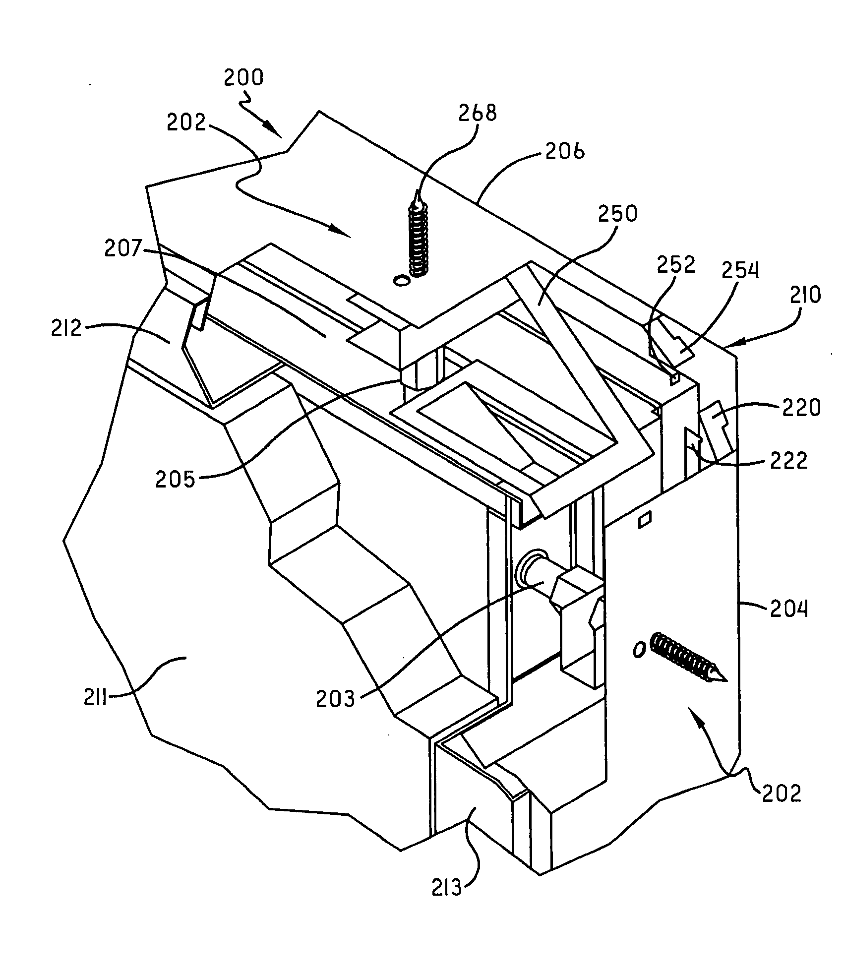
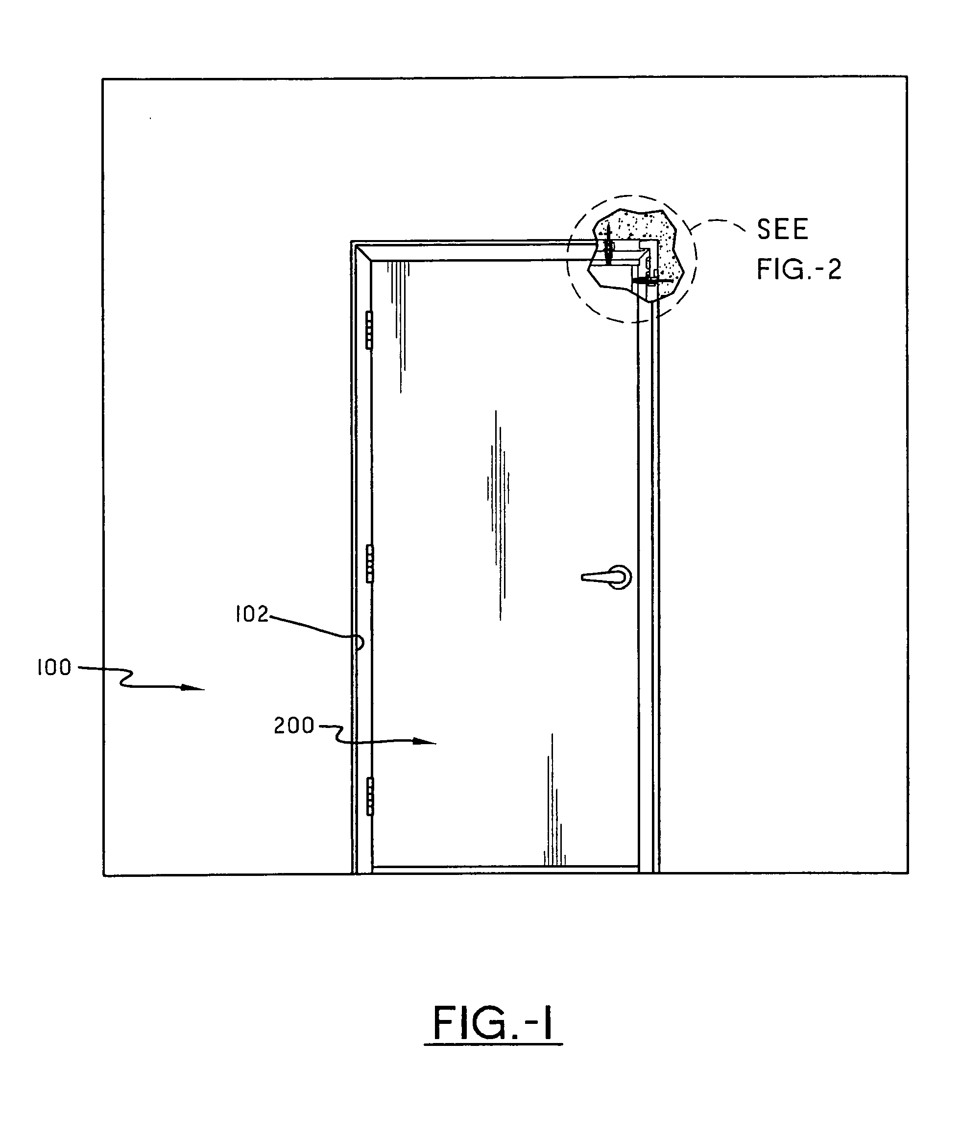
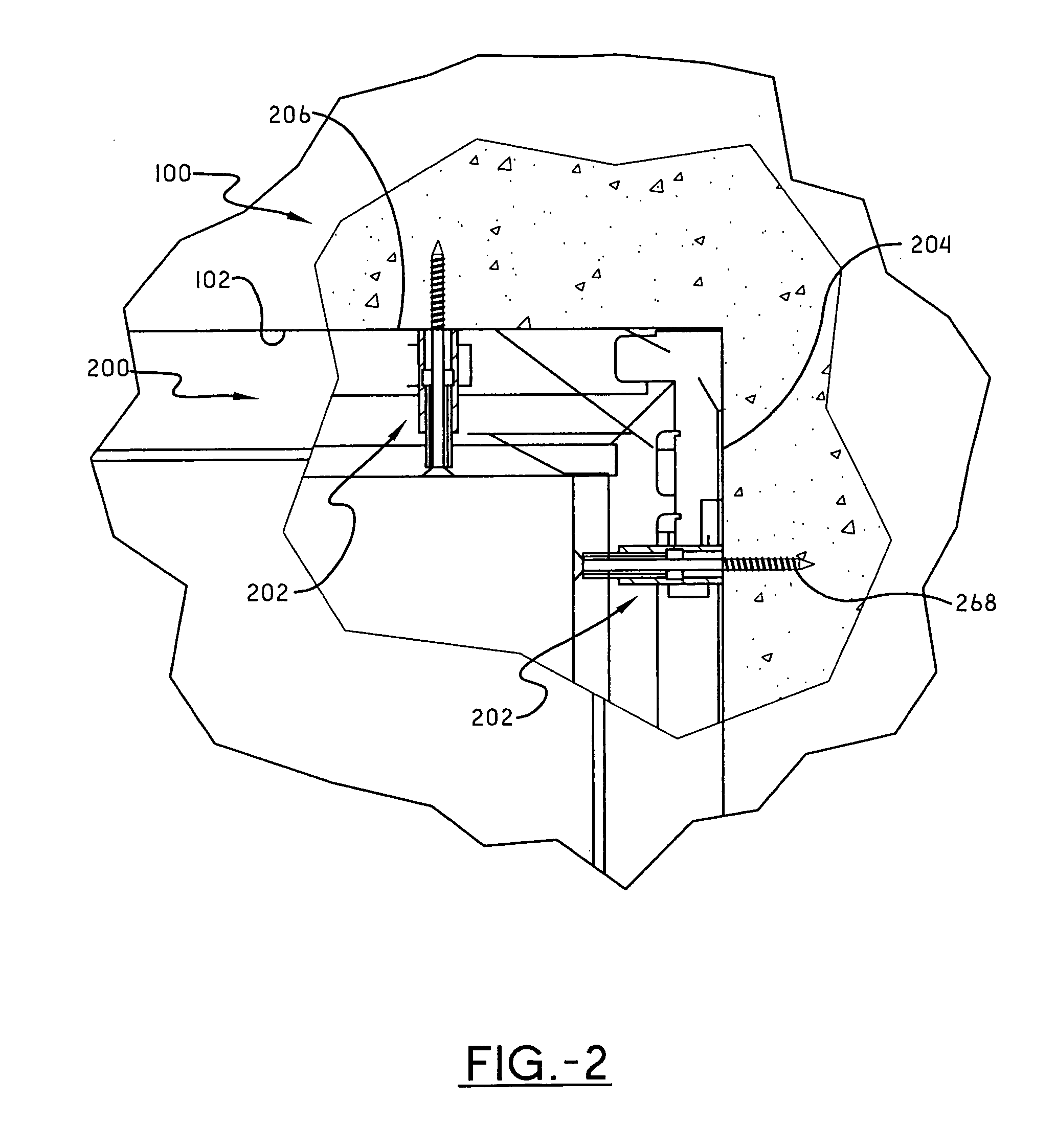
[0028]FIG. 1 shows a rigid wall section 100 having an adjustable door frame system 200 positioned therein. As can be seen, an opening 102 in the wall section 100 is configured to receive the adjustable door frame system 200. To aid in installation, the opening 102 in the wall section 100 is slightly larger than the minimum dimensions of the adjustable door frame system 200. This is typical of masonry construction for door installati...


PUM


Abstract

An adjustable door frame system includes at least one vertical frame member having a movable vertical subjamb assembly capable of outward movement relative the vertical frame member. The adjustable door frame system also contains a horizontal frame member having a movable horizontal subjamb assembly capable of outward movement relative the horizontal frame member. The door frame system also contains a plurality of adjusting mechanisms coupling the vertical subjamb assembly and horizontal subjamb assembly to the frame members. Each adjusting mechanism includes a hex nut connected to its subjamb assembly with a hex nut clip, and a hollow set screw and guide tube. Rotation of the hollow set screw causes the hex nut to move axially along the guide tube thereby causing the hex nut clip and its connected subjamb assembly to be adjusted outwardly with respect to the door frame system, thereby filling a gap between its frame member and the wall section. After each adjustment mechanism is adjusted as desired, a threaded masonry anchor is inserted through the guide tube, the hollow set screw and the hex nut and into the wall section to fasten the door frame system to the wall section.

Description

CROSS REFERENCE TO RELATED APPLICATION[0001]This application claims the priority benefit of U.S. Provisional Patent Application Ser. No. 60 / 958,483 filed Jul. 6, 2007.BACKGROUND OF THE INVENTION[0002]1. Field of Invention[0003]This invention relates to the use of a pre-assembled metal frame door system for installation into an existing building opening where the walls are made of rigid material such as concrete.[0004]2. Description of Related Art[0005]Concrete openings offer a challenge for installing door systems because it is difficult to precisely control the size of the opening such that a pre-assembled door system can be installed quickly without the use of shims. Two generally common methods are used to create an opening in a concrete wall. One method is to position a form slightly larger than the door frame within a larger wall form as the concrete is poured to create the wall section. The void created by the door form creates the required opening once the form is removed. Th...

Claims


Application Information

Patent Timeline
IPC IPC(8): E06B1/52F16B35/06E04B1/35
CPCE06B1/52F16B35/06E06B1/56
Inventor WAGNER, JEFFREY P.SMIGEL, JOAN
Owner THERM ALL
Features
  • Generate Ideas
  • Intellectual Property
  • Life Sciences
  • Materials
  • Tech Scout
  • Unparalleled Data Quality
  • Higher Quality Content
  • 60% Fewer Hallucinations
Learn More