Stenting Ring with Marker

a marker and stent technology, applied in the field of stents, can solve the problems of sacrificing the stenting force and not being attractive to stent designers, and achieve the effects of enhancing the bond between the stent and the marker, enhancing the luminexx technology, and being secure and precis

Active Publication Date: 2010-03-18
CR BARD INC
View PDF99 Cites 39 Cited by
  • Summary
  • Abstract
  • Description
  • Claims
  • Application Information

AI Technical Summary

Benefits of technology

[0011]In our already published WO2002 / 015820, it is taught how to take advantage of laser cutting technology applied to a tubular workpiece to enhance the bond between a stent and a marker. The laser naturally produces frusto-conical joining surfaces on the stent and the marker, which can be brought together at an interface between the stent and a marker that is relatively secure and precise. That technology is now known to those skilled in the art, by virtue of the successful LUMINEXX stent that has been on the market for some considerable time. The present invention can therefore be looked upon as an enhancement of LUMINEXX technology.
[0012]With ever-increasing performance of laser cutting equipment, dimensional tolerances become ever more refined, allowing an ever more precise “fit” between stent and marker, with deliberate inclusion in the design concept of strain when stent and marker are brought into engagement with each other, by imposing a chosen degree of elastic stress on the material that backs each interface between the stent and a marker thereby to increase the level of assurance that the bond between stent and marker is secure.

Problems solved by technology

Every increment in thickness in the radial extent of the stent annulus is detrimental to the ability of the stent to be transluminally delivered along narrow and tortuous bodily lumens and will require larger sized delivery systems.
One problem with reducing the radial thickness of the stent annulus is that stenting force is sacrificed.
Thus, it is not attractive to stent designers to accept any local or global increase of radial thickness to accommodate a marker.

Method used


Image

  • Stenting Ring with Marker
  • Stenting Ring with Marker
  • Stenting Ring with Marker

Examples


Embodiment Construction

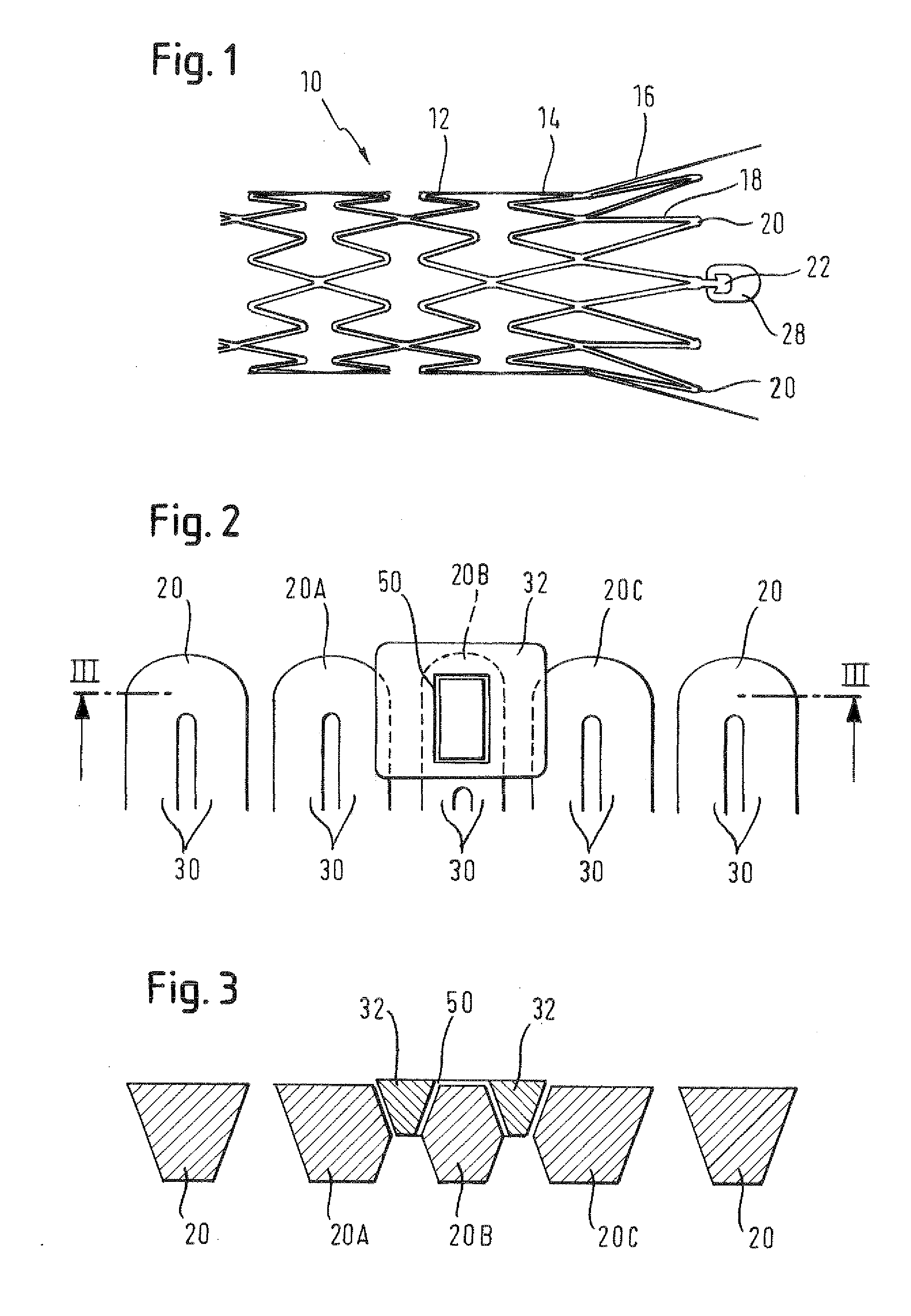
[0020]Looking first at FIG. 1, this is part of a drawing taken from applicant's WO 02 / 15820 and the reader is referred to that WO document for a detailed description of the content of the Figure. A self-expanding stent 10 of nickel-titanium shape memory alloy exhibits zig-zag stenting rings, such as 12 and 14, that are shown in FIG. 1 in an expanded configuration, after deployment in bodily tissue. The end ring 16 has longer struts 18 than our present inner rings 12 and 14 and, where two end struts 18 come together at nodes 20 is the axial extent of the stent lumen. Cantilevered from just 4 of the 12 end nodes 20, on a carrier portion 22, is a radiopaque tantalum marker spoon 28. As explained in the WO document, when the stent 10 is in the radially compact delivery disposition, the ring of 4 tantalum marker spoons 28 cantilevered on the end of the stent forms virtually a full circle of tantalum metal in the catheter delivery system for the stent, rendering it relatively easy for the...


PUM


Abstract

A stenting ring made of a tube or rolled-up sheet that has a characteristic wall thickness. The ring defines a lumen and is equipped with at least one marker made of a material different from that of the ring. The ring is expansible from a radially compact disposition with a relatively small circumference to a radially expanded disposition with a relatively large circumference. The ring exhibits in the compact disposition a serpentine arrangement of succeeding struts lying in alternate opposite directions to the longitudinal axis of the lumen. The marker has a thickness in the radial direction of the ring that is less than the characteristic wall thickness, and has a width that extends circumferentially around an arc of the ring. The marker is attached to the ring at a zone located at a point intermediate in the extent of said arc. The marker overlaps with a respective one of said struts, at each end of its circumferential arc, when the ring is in the compact disposition, the respective struts moving away from each other, and from the marker, when the ring expands towards said radially expanded disposition.

Description

TECHNICAL FIELD[0001]This invention relates to a stenting ring made of a tube or rolled-up sheet that has a characteristic wall thickness the ring defining a lumen and being equipped with at least one marker made of a material different from that of the ring, the ring being expansible from a radially compact disposition with a relatively small circumference to a radially expanded disposition with a relatively large circumference, the ring exhibiting in the compact disposition a serpentine arrangement of succeeding struts lying in alternate opposite directions to the longitudinal axis of the lumen.BACKGROUND ART[0002]Stenting rings on the market are made from biologically compatible metals such as stainless steel or nickel-titanium shape memory alloy and, as these materials are relatively poorly visible in x-ray images, they are often equipped with “markers” that are more opaque to x-rays thereby allowing the radiologist to monitor the position of the stent in a bodily lumen. It is a...

Claims


Application Information

Patent Timeline
Patent Type & Authority Applications(United States)
IPC IPC(8): A61F2/82A61F2/915
CPCA61F2/915A61F2002/91591A61F2250/0036A61F2230/0067A61F2230/005A61F2230/0054A61F2250/0098
Inventor WACK, THILOSUPPER, WOLFGANG
Owner CR BARD INC
Why Eureka
Try Eureka