Manufacturing Method of Pneumatic Tire

a manufacturing method and tire technology, applied in the field of pneumatic tire manufacturing, can solve the problems of reducing the uniformity of the tire, and increasing the winding man hour, so as to improve production efficiency, shorten the forming time, and secure the forming precision of the tir

Inactive Publication Date: 2009-01-29
TOYO TIRE & RUBBER CO LTD
View PDF3 Cites 4 Cited by
  • Summary
  • Abstract
  • Description
  • Claims
  • Application Information

AI Technical Summary

Benefits of technology

[0016]In the above method, it is preferable that the carcass ply in the fourth step is in a state in which a center portion is evaginated to an outer side in a diametrical direction and an end portion is wound up. Therefore, it is possible to preferably secure the forming precision of the tire while suppressing the shape change of the compound rubber member.
[0017]The present invention is particularly useful in the case that the first and second rubber members are constituted by the annular evaginating portion formed so as to evaginated to an outer side in the tire width direction of a bead portion. Because the annular evaginating portion tends to include a lot of parts, and there is a tendency that the man hour is increased in accordance with the conventional manufacturing method and the tire forming work is complicated, however, the present invention mentioned above can shorten the forming time so as to improve the production efficiency.

Problems solved by technology

However, in this method, since the joint portion becomes locally thick due to a superposition or a close contact between the end portions, a shape of the rubber member becomes non-uniform in a circumferential direction, and there is a problem that a uniformity of a tire is lowered.
However, in accordance with this method, although a shape uniformity of the rubber member is improved, a winding man hour is increased and a forming time becomes long.
In addition, there is a problem that a crack tends to be generated along an interface of the rubber ribbon.

Method used


Image

  • Manufacturing Method of Pneumatic Tire
  • Manufacturing Method of Pneumatic Tire
  • Manufacturing Method of Pneumatic Tire

Examples


Embodiment Construction

[0023]An embodiment of the present invention will be explained with reference to the drawings.

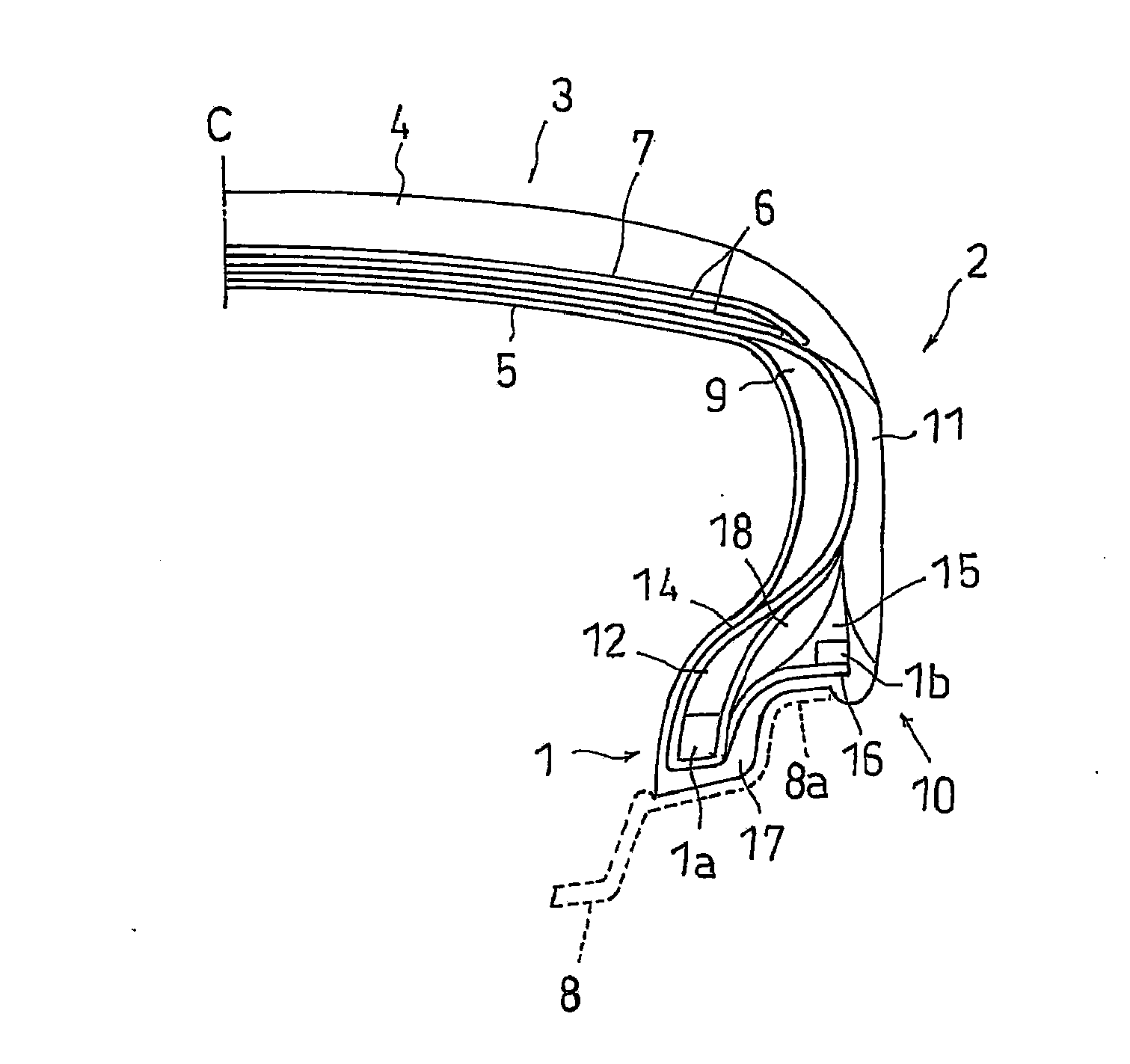
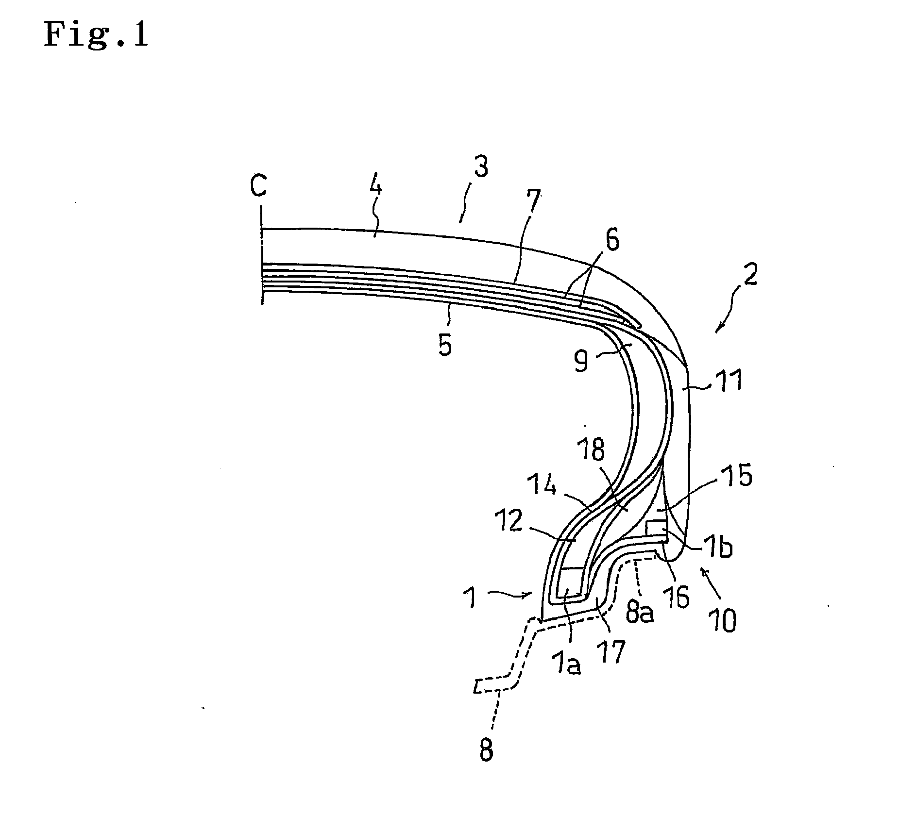
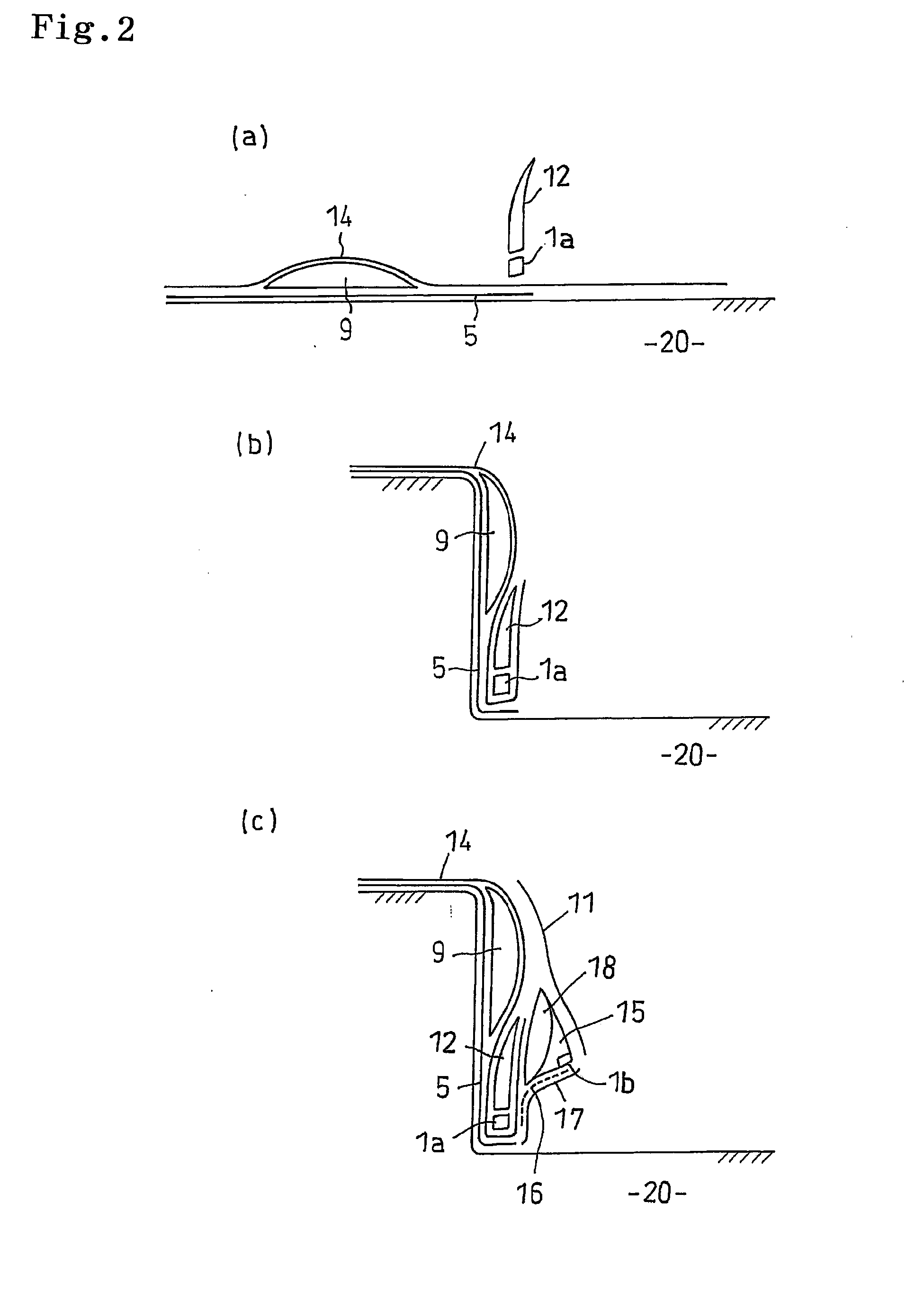
[0024]FIG. 1 is a half cross sectional view of a tire meridian line showing one example of a pneumatic tire manufactured by the present invention. The pneumatic tire comprises a pair of bead portions 1, sidewall portions 2 extending from respective bead portions 1 radially outward of the tire, and a tread portion 3 provided between the sidewall portions 2. In the bead portion 1, there are arranged an annular bead 1a constituted by a convergence body of bead wire consists of a steel wire or the like, and a bead filler 12 formed as a triangular cross sectional shape in an outer side in a tire diametrical direction of the bead 1a, and an end portion of a carcass ply 14 is wound up to an outer side in such a manner as to pinch them.

[0025]An inner liner rubber 5 for retaining a pneumatic pressure is arranged in an inner peripheral side of the carcass ply 14. Further, a rim strip rubber 17 is arr...


PUM

PropertyMeasurementUnit
angleaaaaaaaaaa
widthaaaaaaaaaa
shapeaaaaaaaaaa

Abstract

A side surface of an apex rubber is exposed annularly by injection molding the annular apex rubber and opening a forming mold while retaining the annular apex rubber in an unvulcanized state. Further, a side surface of a rubber pad is exposed annularly by injection molding the annular rubber pad and opening a forming mold while retaining the annular rubber pad in an unvulcanized state. Thereafter, an integrated compound rubber member is formed by overlapping a lower mold retaining the apex rubber and a lower mold retaining the rubber pad and laminating the side surface of the apex rubber to the side surface of the rubber pad, and an unvulcanized tire is formed by laminating the compound rubber member to the carcass ply.

Description

FIELD OF THE INVENTION [0001]The present invention relates to a manufacturing method of a pneumatic tire including a step of forming an unvulcanized tire (green tire) by laminating a plurality of rubber members on a carcass ply formed as a tubular shape.DESCRIPTION OF THE RELATED ART [0002]A pneumatic tire is a rubber compound constructed by laminating various rubber members to inner and outer sides of a framework constituted by a carcass ply, and a plurality of rubber members are laminated to a tubular formed carcass ply at manufacturing line in a manufacturing step, whereby an unvulcanized tire is formed. These rubber members include a rubber member which is wound around a forming drum or a carcass ply online so as to be formed as an annular shape or a cylindrical shape, and a rubber member which is previously formed as an annular shape in accordance with an offline manufacturing so as to be fed to a manufacturing line at a necessary timing.[0003]The rubber member which can be man...

Claims


Application Information

Patent Timeline
Patent Type & Authority Applications(United States)
IPC IPC(8): B29D30/32
CPCB29C45/1459B29D30/0678B29L2030/001B29D30/72B29D2030/724B29D30/32
Inventor SEGAWA, MASAHIRO
Owner TOYO TIRE & RUBBER CO LTD
Why Eureka
Try Eureka