Symmetrical self-closing mechanism for a drawer slide

a drawer slide and self-closing technology, applied in the field of self-closing drawer slide, can solve the problems of affecting the operation of the drawer slide, the indentation of the channel, the cost of failure, etc., and achieve the effect of simple operation and inexpensive manufacturing

Active Publication Date: 2009-01-29
WATERLOO FURNITURE COMPONENTS
View PDF8 Cites 16 Cited by
  • Summary
  • Abstract
  • Description
  • Claims
  • Application Information

AI Technical Summary

Benefits of technology

[0009]It is an object of the present invention to provide a self-closing drawer slide having a catch that is slidable within a channel of a housing that is simple to operate and inexpensive to manufacture in one piece with no components of the catch that move relative to one another except when the re-set feature operates. It is a further object of the present invention to provide a catch and latch arrangement that is durable and has a fail safe reset feature.

Problems solved by technology

The cam slide of Lee is relatively complex, expensive and subject to failure and it contains components that move relative to other components of the cam slider.
While the channel of Lee is generally straight, the channel has two indentations to accommodate a reset feature that is also complex and subject to failure, particularly as the cam slider becomes worn with use.
Previous devices are complex, expensive, or they do not function properly as the actuator and hook disengage prematurely or cannot be easily reset when the slide moves to the inner end of the housing before engagement with the actuator, or they only function properly when manufactured within strict tolerances, or they fail to function properly when the actuator and hook become slightly worn through usage.
Previous self-closing drawer slides that have a reset feature often have an actuator being forced over a hook, thereby increasing the wear between the actuator and the hook, or stretching these components if they are made to be flexible and thereby reducing the proper operation of the self-closing assembly, or causing the assembly to fail prematurely.
Further, some previous devices have an actuator that only weakly engages a hook and when the drawer in which the slide is used is opened too quickly by a user, the actuator and hook disengage prematurely, causing the hook to move to the inner end of the housing under the force of the spring, and requiring the assembly to be reset before it can operate when the drawer is closed.

Method used


Image

  • Symmetrical self-closing mechanism for a drawer slide
  • Symmetrical self-closing mechanism for a drawer slide
  • Symmetrical self-closing mechanism for a drawer slide

Examples


Embodiment Construction

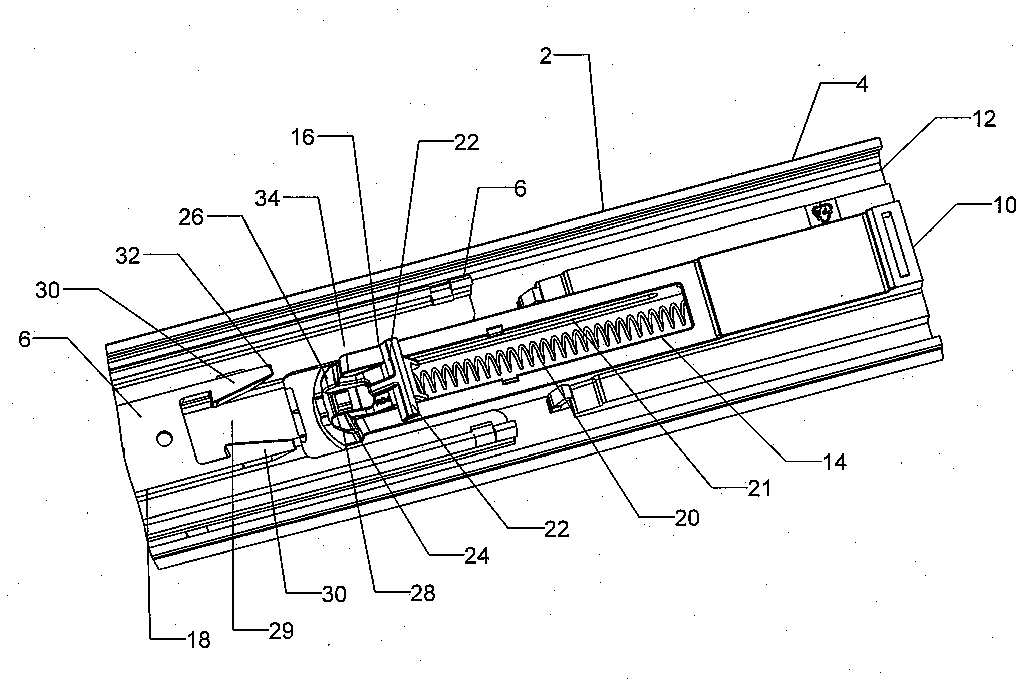
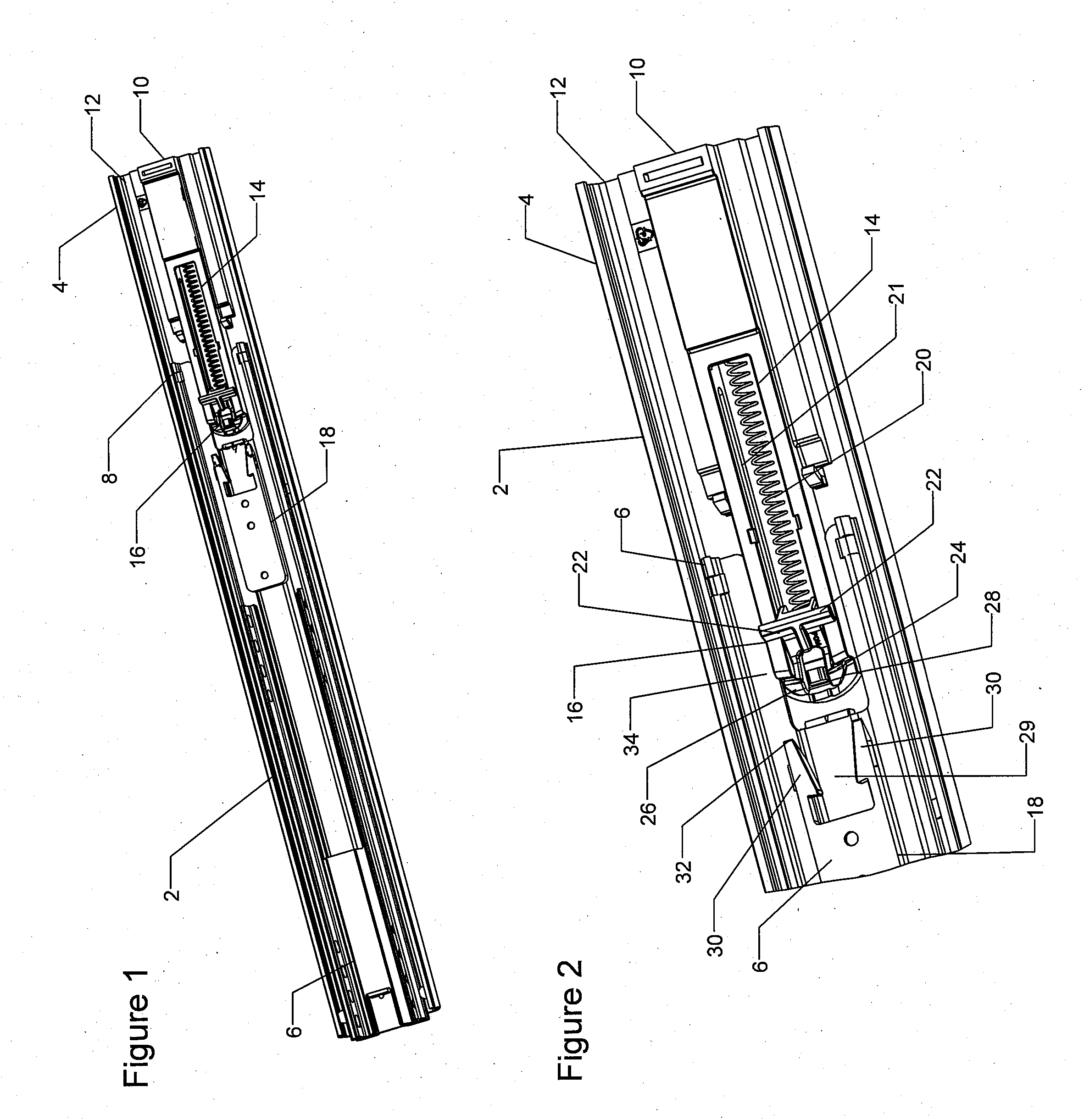
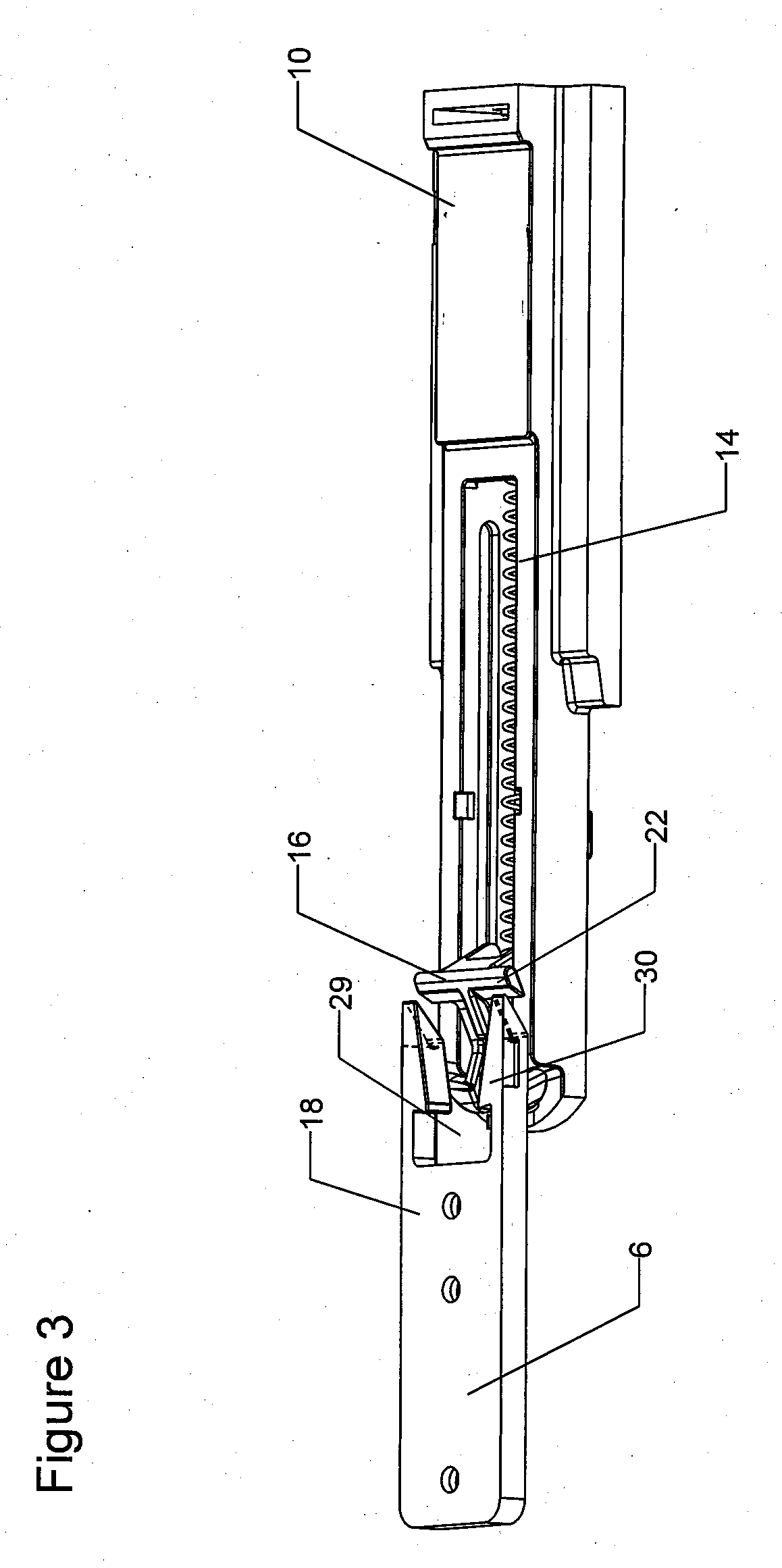
[0019]In FIG. 1, a drawer slide 2 has a plurality of longitudinal sections that telescopingly slide relative to one another. The sections are an outer section 4, an inner section 6 and an intermediate section 8. A housing 10 is affixed to an inner end 12 of the outer section 4. The housing 10 has a linear longitudinal channel 14 with a catch 16 shown in a locked position at an outer end of the housing 10. The inner section 6 has a latch 18 at an inner end thereof. The slide 2 is in an open position.

[0020]FIG. 2 is an enlarged perspective view of an inner end of the slide 2. The channel 14 contains a spring 20 that is connected to the catch 16 and biases the catch to slide along the channel 14 toward the inner end of the channel when the catch is in an unlocked position. The spring is connected to the inner end of the housing 10 but could alternatively be connected to the inner end 12 of the outer section 4. The catch in FIG. 2 is in a locked position. The catch rocks longitudinally ...


PUM


Abstract

A self-closing drawer slide has a housing with a linear channel extending therein at an inner end of an outer longitudinal section. A catch is slidably mounted within the channel and has pivot pins 36 extending out either side thereof (only one side is shown) into corresponding slots in the sides of the channel. The catch is symmetrical about a longitudinal centre line of the housing and rocks rearward to unlock and engage a latch on an inner longitudinal section and forward to lock and release the latch. The catch is biased to slide to an inner end of the channel when the catch is unlocked and there are no external forces on the slide.

Description

[0001]Applicant claims the benefit of U.S. Provisional Application Ser. No. 60 / 951,878 filed on Jul. 25, 2007.BACKGROUND OF THE INVENTION[0002]1. Field of the Invention[0003]This invention relates to a self-closing drawer slide having a housing mounted on an inner end thereof with a catch in the housing that engages a latch on an inner section of the slide to move the slide to a closed position when the inner section moves within a pre-determined distance of the closed position.[0004]2. Description of the Prior Art[0005]It is known to have self-closing drawer slides with a housing affixed at an inner end of the outer slide member. In the Lee U.S. Pat. No. 7,083,243 issued Aug. 1, 2006, the housing has a channel with a cam slider 20 that operates by a leaf spring to move engaging jaws laterally to lock and unlock the cam slider within the channel and to simultaneously disengage and engage respectively an actuating pin in the inner slide member. The cam slide of Lee is relatively comp...

Claims


Application Information

Patent Timeline
Patent Type & Authority Applications(United States)
IPC IPC(8): A47B88/04A47B88/49
CPCA47B88/047A47B88/467
Inventor JURJA, SAMUEL
Owner WATERLOO FURNITURE COMPONENTS
Why Eureka
Try Eureka