Root-cause approach to problem diagnosis in data networks

Active Publication Date: 2009-01-29
EG INNOVATIONS PTE
View PDF6 Cites 89 Cited by
  • Summary
  • Abstract
  • Description
  • Claims
  • Application Information

AI Technical Summary

Benefits of technology

[0023]The method may further operate so that those indicative problems relating to the layer upon which all other layers are

Problems solved by technology

However, the recent increased utilisation of virtual machines as part of data networks has resulted in the diagnostic approach recited therein no longer providing a proper assessment of potential root-cause problems.
Accordingly, a malfunctioning application running on one virtual machine may result in other virtual machines hosted on the same physical computer system being starved of resources which should otherwise be available to them.
Similarly, abnormal processes on the physical computer system may result in poor

Method used


Image

  • Root-cause approach to problem diagnosis in data networks
  • Root-cause approach to problem diagnosis in data networks
  • Root-cause approach to problem diagnosis in data networks

Examples


Embodiment Construction

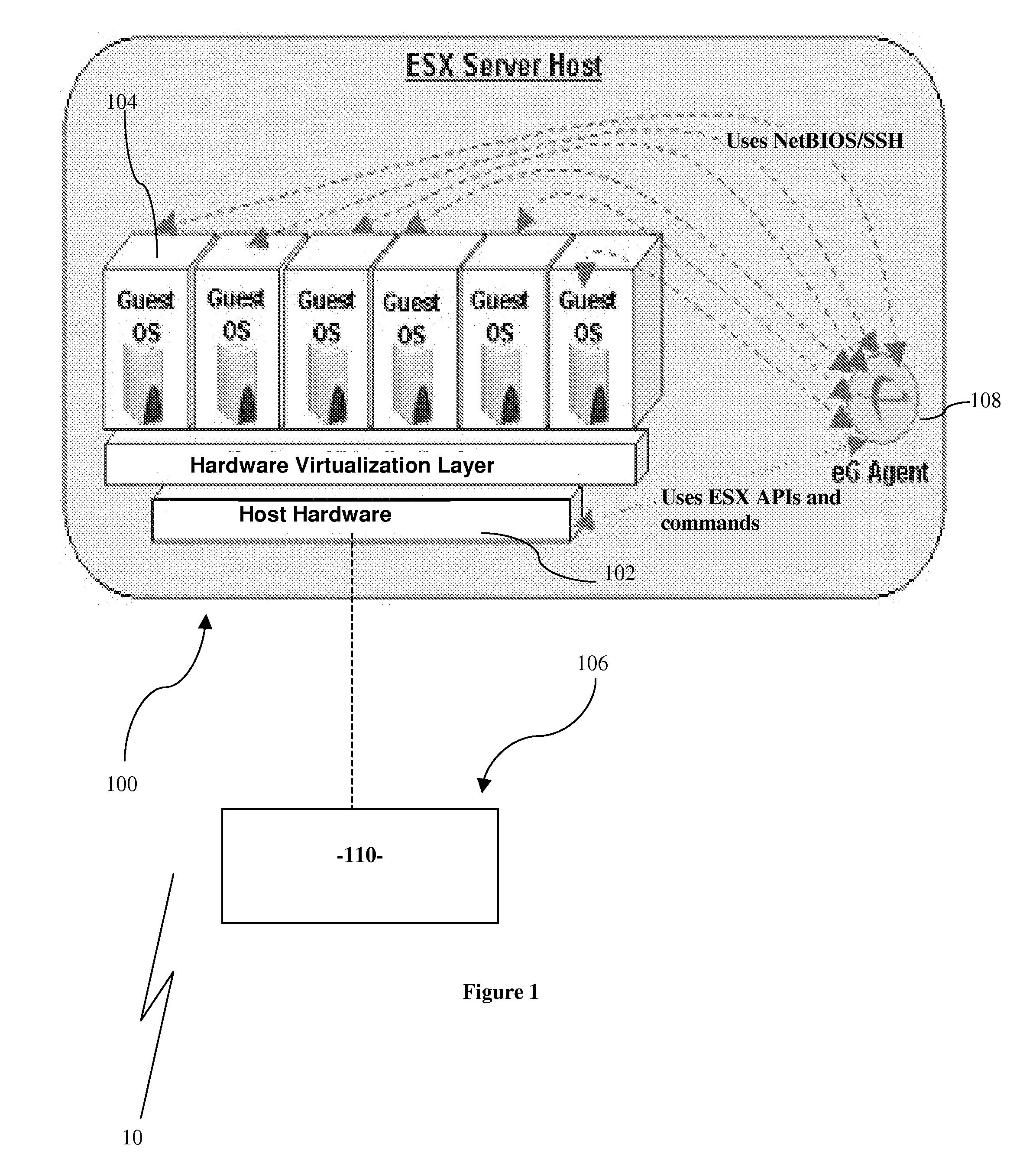
[0032]In accordance with a first embodiment of the present invention there is an improved root cause diagnostic process 10. The root cause diagnostic process 10 operates to diagnose problems in a data network 100. The data network 100 includes at least one physical machine 102 and at least one virtual machine 104. The virtual machines 104 may be hosted by one or more of the at least one physical machines 102.

[0033]The invention will be described with reference to a monitoring system 106 operable to provide certain metrics relating to the physical machines 102 and virtual machines 104. With respect to this particular embodiment, the monitoring system concerned is the monitoring system as described in the first embodiment of the applicant's co-pending application entitled “Monitoring System for Virtual Application Environments” having the same priority date as the present application.

[0034]The monitoring system 106 as described in the co-pending application is slightly modified in pro...


PUM


Abstract

An improved root-cause approach to problem diagnosis in data networks in the form of a method comprising the steps of: associating each metric in a at least one set of metrics with at least one component and/or network device; obtaining values for each such metric from a monitoring system; determining whether each such metric is indicative of a problem within the data network; and ranking and correlating indicative problems to determine whether a problem may be symptomatic of another problem based on an interconnection and/or interdependency between a physical machine and a virtual machine, between components or between components and network devices.

Description

CROSS-REFERENCE[0001]This application claims benefit of priority to U.S. application Ser. No. 11 / 781,156, and its corresponding PCT International Application entitled “Monitoring System for Virtual Application Environments”, both filed on Jul. 20, 2007, which are hereby incorporated by reference.FIELD OF THE INVENTION[0002]The invention relates to an improved root-cause approach to problem diagnosis in data networks. The invention is particularly suited to diagnosing problems in a data network including at least one virtual machine.BACKGROUND TO THE INVENTION[0003]The following discussion of the background to the invention is intended to facilitate an understanding of the present invention. However, it should be appreciated that the discussion is not an acknowledgment or admission that any of the material referred to was published, known or part of the common general knowledge in any jurisdiction as at the priority date of the application.[0004]In U.S. Pat. No. 6,701,459, the applic...

Claims


Application Information

Patent Timeline
IPC IPC(8): H04L12/26
CPCG06F11/079G06F11/0712
Inventor KANNAN, RAJARAMANATHAN, SRINIVASSUBRAMANIAN, SREEDHARANVAIDHINATHAN, BALAMURUGAN
Owner EG INNOVATIONS PTE
Why Eureka
Try Eureka