
Joint and/or Bearing Arrangement

a bearing arrangement and joint technology, applied in the direction of rod connections, couplings, tractors, etc., can solve the problems of limiting the excursion of the bellow, limiting the expansion of the bellow, and often at risk of external mechanical damage to the cover of the joint and/or bearing arrangement. the effect of reducing the movement of the pin

Inactive Publication Date: 2009-01-29
ZF FRIEDRICHSHAFEN AG
View PDF12 Cites 4 Cited by
  • Summary
  • Abstract
  • Description
  • Claims
  • Application Information

AI Technical Summary

Benefits of technology

[0010]The object is obtained with the invention with a separate protective cover which is placed around the sealing collar and conforms to the shape of the sealing collar. Forming the cover separately allows the cover to move relative to the sealing collar, enabling a large pin excursion. Unlike with a co-extruded outer layer or with a more or less rigid outer bell, movement is not restricted. An injection molded bellow can also be easily unmolded, because the protective cover is placed only over the finished bellow.
[0019]Due to its high elasticity, the protective cover can be attached to both axial ends of the sealing collar with ring-shaped fastening elements, without restricting joint movement.

Problems solved by technology

When such joint and / or bearing arrangements are installed in vehicles, particularly for use in forestry and / or all-terrain vehicles, for example in tractors, off-road vehicles, Unimogs, military vehicles and the like, the covers of the joint and / or bearing arrangements are frequently at risk of suffering external mechanical damage, for example by stones or branches, in particular with freestanding axles.
However, this solution reaches its limits with bellow-shaped covers that have large differences in diameter between the protruding bulges and the undercuts, in particular when the pin excursion should have a large angular range, because the outer layer then lacks sufficient elasticity.
However, this type of cover limits the excursion of the bellow.
In addition, a greater pin excursion introduces severe wear due to friction at points between the outwardly protruding rings and the bell-shaped cover.

Method used


Image

  • Joint and/or Bearing Arrangement
  • Joint and/or Bearing Arrangement
  • Joint and/or Bearing Arrangement

Examples


Embodiment Construction

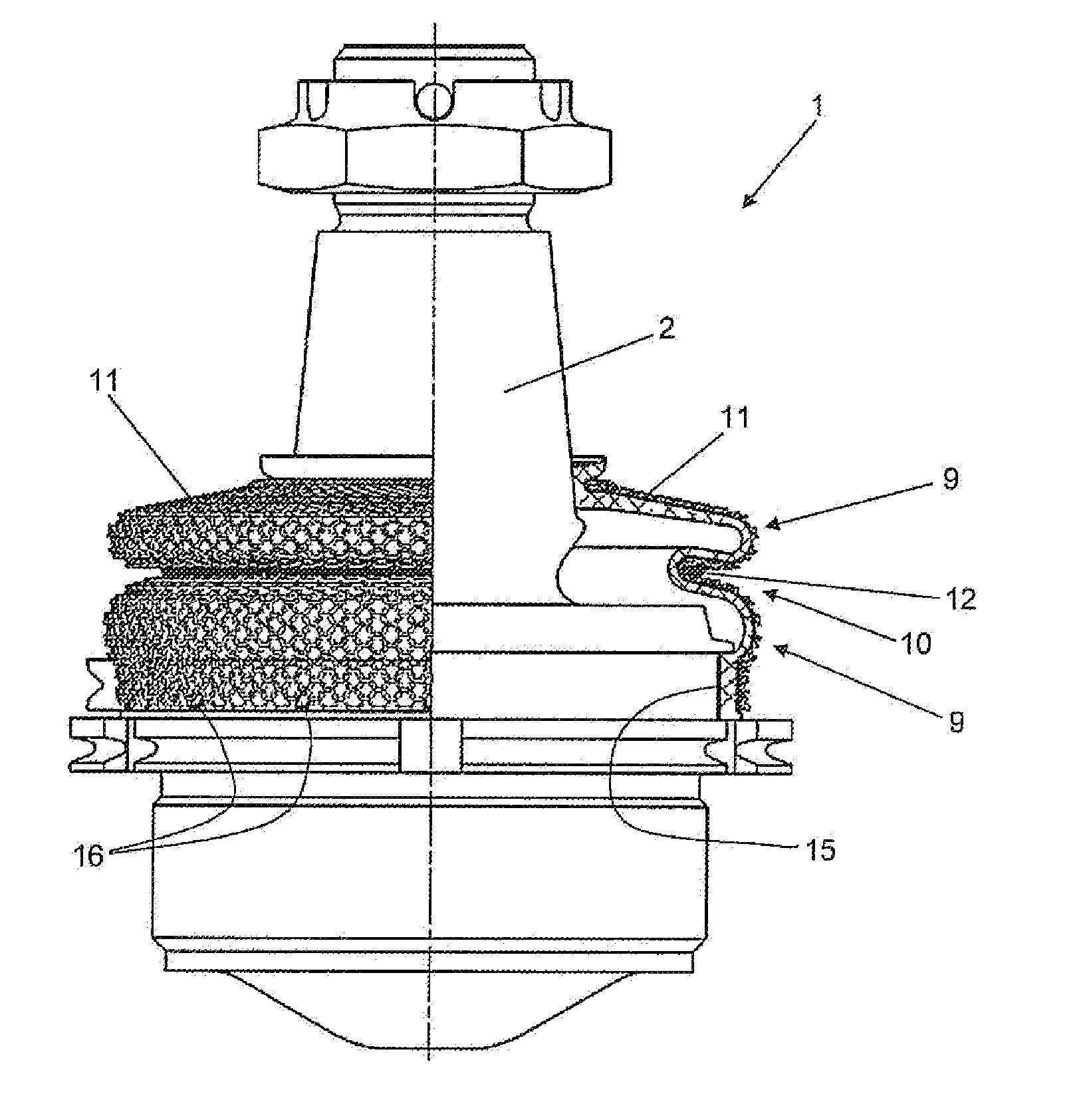
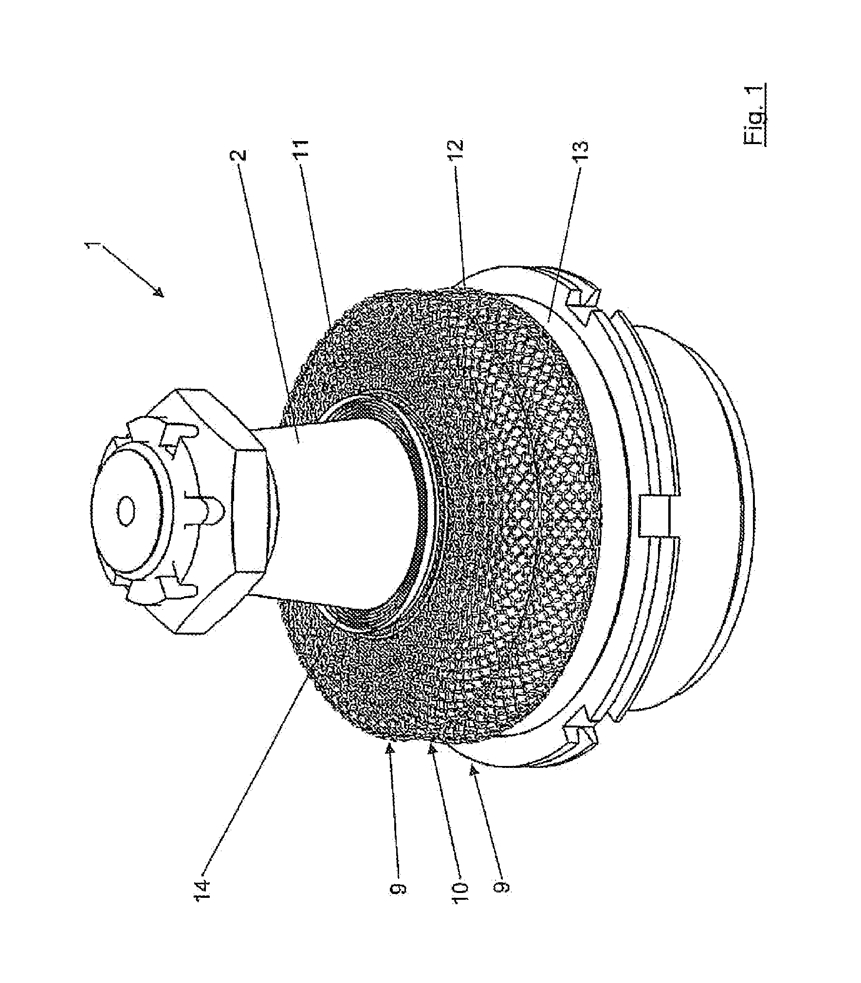
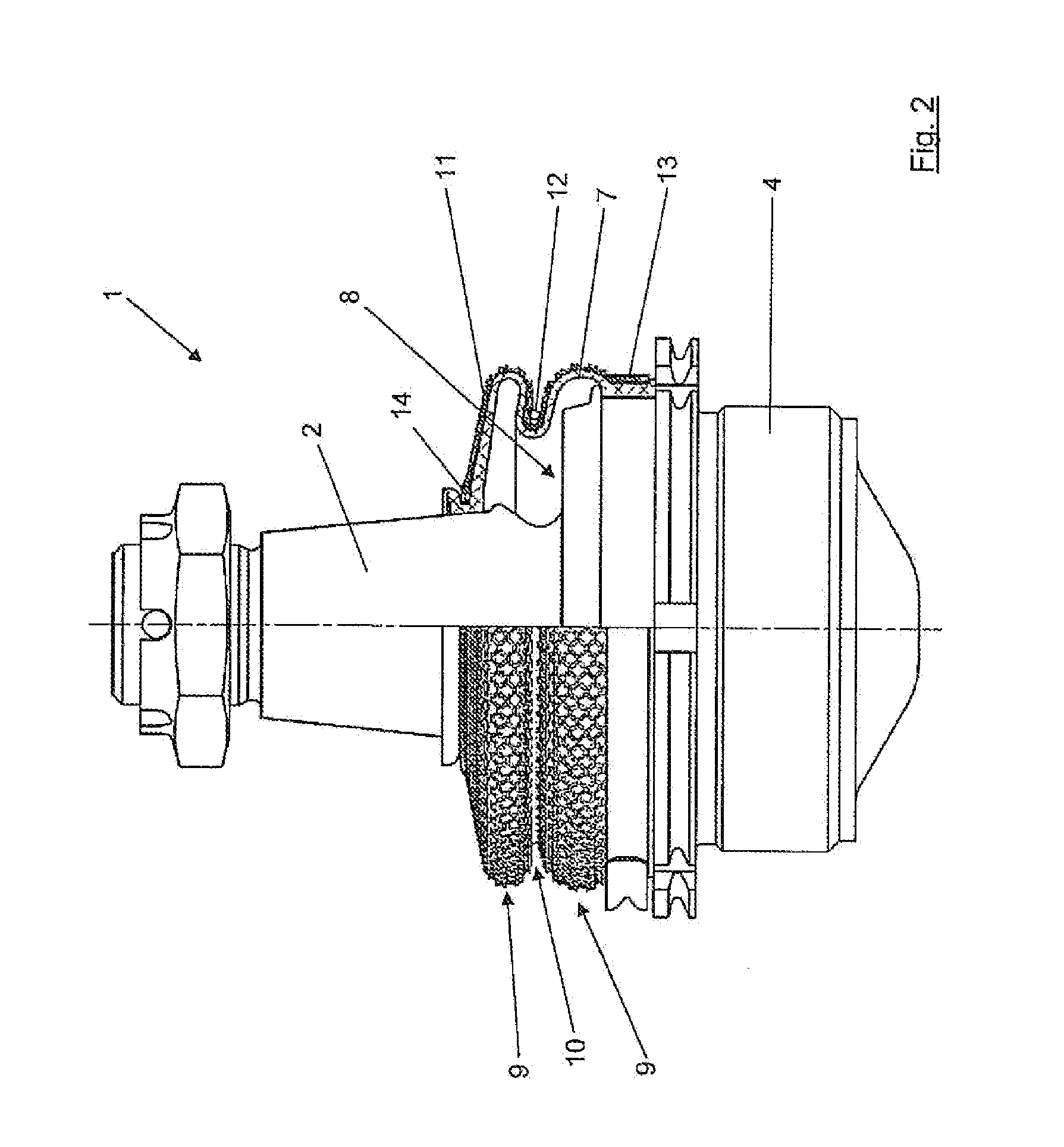
[0030]The pivot arrangement 1 according to FIG. 1 includes an axially extending pivot pin 2 with an enlarged head region 3 which is formed, for example, as a substantially spherical formed part. The head region 3 can be held in and in relation to a typically permanently lubricated joint socket inside a receiving a housing (joint socket) 4, which receives the head region, enabling swivel and / or tilt motion. The joint socket 4 can be essentially closed or preferably ring-shaped and formed outside the pin opening. Such tilt motion of the pin 2 with respect to the joint socket 4 is illustrated in FIG. 7.

[0031]The radially outer part of the joint socket 4 is in turn surrounded at least in part by a receiving space operating as a housing 5. Joint socket 4 and receiving space 5 together form a bearing assembly. The housing 5 need not be a separate component, but can also be an integral part of a connecting rod 6 which surrounds, for example, the installed pivot arrangements 1, as shown in ...


PUM


Abstract

A joint and / or bearing arrangement (1) with a pivot pin (2), in particular with a pivot pin (2) having a head region (3) which is movable with respect to a receiving joint socket (4), wherein the pivot pin (2) is at least partially surrounded by a circumferential sealing collar (7), is configured so that the outside of the sealing collar (7) is covered by a separate protective cover (11) which conforms to the shape of the sealing collar.

Description

BACKGROUND OF THE INVENTION[0001](1) Field of the Invention[0002]The invention relates to a joint and / or bearing arrangement according to the preamble of claim 1 as well as a motor vehicle with one or several joint and / or bearing arrangements of this type, in particular in chassis and / or for steering components.[0003](2) Description of Related Art[0004]In joint arrangements having a moveably supported pin, for example a pin having an enlarged head region which is supported for relative movement in a joint socket, the region between the head region and the socket subjected to friction must be well sealed against incursion of particles and / or humidity. It is known to surround a large area of the pin over in the axial direction with a sealing collar made of an elastic material such as to allow the sealing collar to conform to the movement of the pin. A sealing collar of this type can be flexibly deformed when constructed as a bellow with ring-shaped bulges and intermediate undercuts.[0...

Claims


Application Information

Patent Timeline
IPC IPC(8): F16C11/06B62D49/06
CPCB60G2204/416F16C11/0671Y10T403/31B60G7/005F16J3/043Y10T403/32041Y10T403/315F16C2326/05
Inventor BRUNNEKE, HANS-GERDLOSCHE, CHRISTIANSCHMUDDE, WERNER
Owner ZF FRIEDRICHSHAFEN AG
Learn More