Insertion system for stents, comprising tension-compression kinematics

US20090030496A1Active Publication Date: 2009-01-29JOTEC

Image

  • Insertion system for stents, comprising tension-compression kinematics
  • Insertion system for stents, comprising tension-compression kinematics
  • Insertion system for stents, comprising tension-compression kinematics

Examples


Embodiment Construction

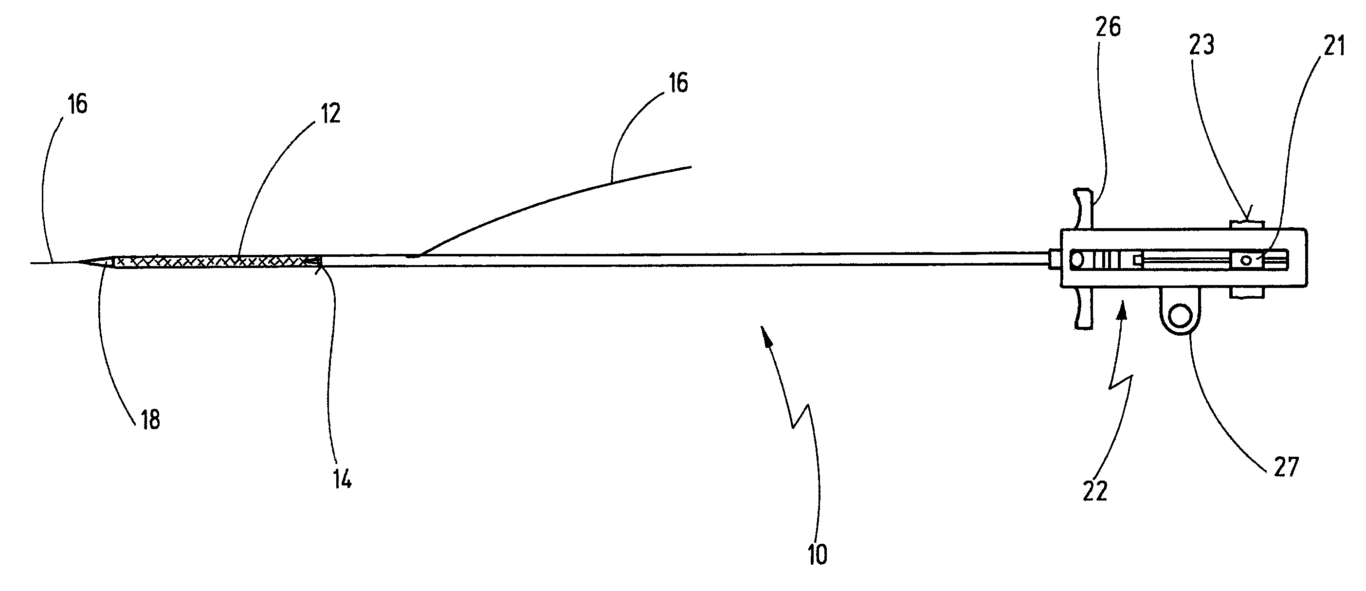
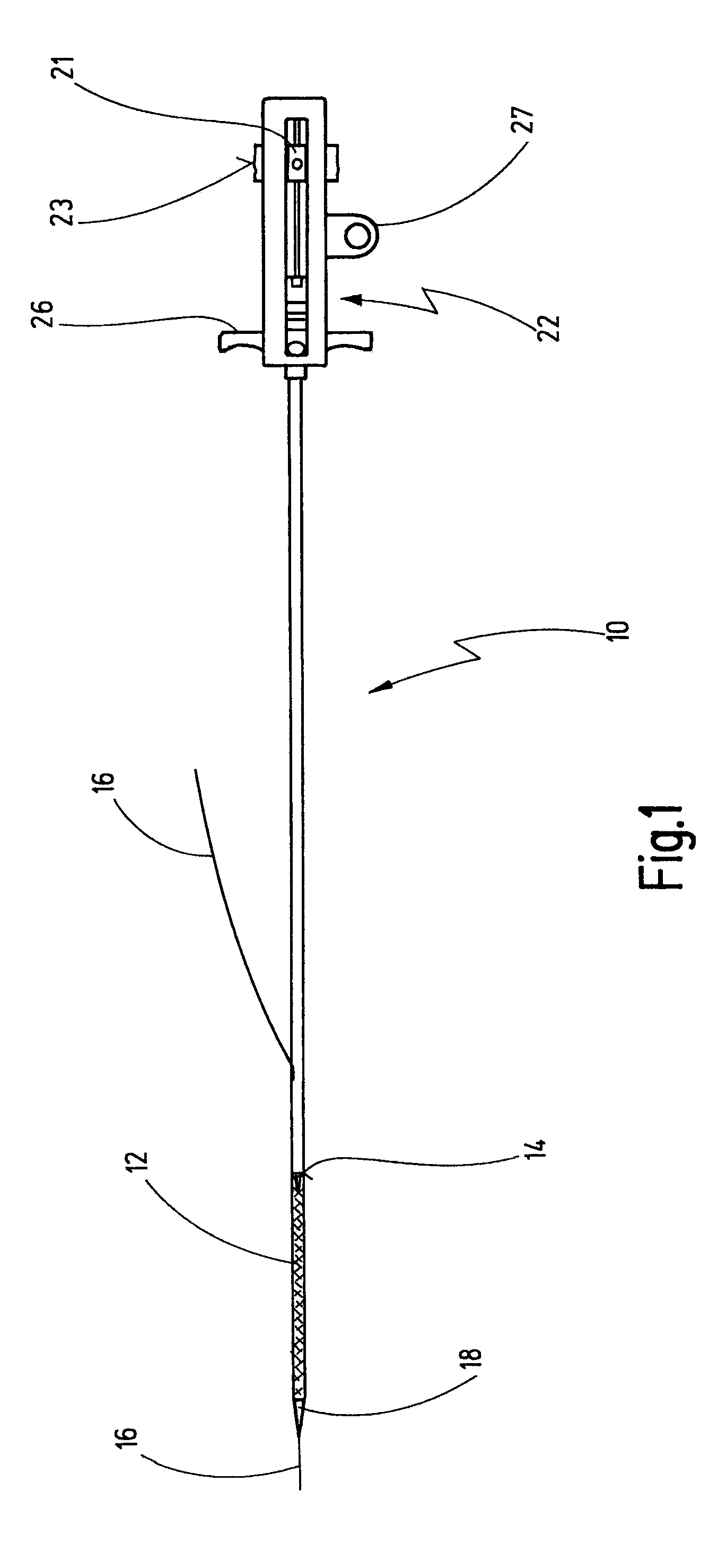
[0096]An insertion system, shown schematically in FIG. 1 and designated overall by reference number 10, can be used to insert a stent or braided stent 12 into a blood vessel.

[0097]The stent 12 can be a self-expanding metal stent that is produced by a plain weaving technique, as is described in the aforementioned DE 103 35 649.

[0098]The insertion system 10 also comprises a tube 14 which keeps the stent 12 radially compressed in the distal part of the tube 14. In this state, the device 10 is introduced into a vessel and placed at the desired position in order to support the vessel with the aid of the stent.

[0099]The insertion system in FIG. 1 also has a grip 22 on which a pulling grip 26 and a thumb hole are also provided. Ends of the flange 21 are also shown, which have a grooved surface 23. FIG. 1 also shows a guide wire 16. With this guide wire 16, the insertion system 10 is introduced into a patient's blood vessel by the known Seldinger technique in order to release the stent 12 t...


PUM


Abstract

The present invention relates to a device for inserting a self-expanding stent into a body vessel. The device comprises a tube, a pushing element and a grip having a housing via which the pushing element is secured on the grip. Further, the device comprises a stent carrier and a moveable element, the latter of which is guided in the housing of the grip and is coupled to the pushing element. Moving the movable element in the proximal direction effects a movement of the pushing element in the distal direction and a movement of the tube in the proximal direction.

Description

CROSS REFERENCE TO RELATED APPLICATIONS[0001]This is a continuation application of International Patent Application PCT / EP2007 / 000403, filed Jan. 18, 2007, designating the United States and published in German as WO 2007 / 085373 A1, which claims priority of German application number DE 10 2006 004 123.2, filed Jan. 25, 2006, whose contents are incorporated herein by reference.BACKGROUND OF THE INVENTION[0002]1. Field of the Invention[0003]The present invention relates to a device for inserting a self-expanding stent into a body vessel, with a tube which, in a distal portion, keeps the stent radially compressed, with a pushing element which is guided in the tube and has a proximal end and a distal end, also with a grip that comprises a housing via which the pushing element is secured displaceably on the grip, and also with a stent carrier which is guided in the pushing element and which has a tip which is mounted fixedly on the device via the grip.[0004]2. Related Prior Art[0005]Such ...

Claims


Application Information

Patent Timeline
29 Jan 2009
Publication
US20090030496A1
IPC
A61F2/06; A61F2/95; A61F2/966
CPC
A61F2/95; A61F2002/9517; A61F2/966; A61F2/9517
Inventors
KAUFMANN, RALF; DERKVIST, STEFAN