[0006]In the inventive linear vibratory conveyor, the utility weight and the counterweight are movably connected to one another, different from the prior art, where both are freely moveable relative to one another. In accordance with the invention, the non-rigid, movable mechanical weight connector forms a vibration amplifying means or contains the means so that it is possible to actively amplify the vibration or movement produced by the drive unit. Thus adequate vibrating amplitudes can be attained even if the drive unit itself has only relatively short vibrating travel. This also permits the use of drive units other than electromagnets, e.g. a piezoelectric drive in which the integrated piezoactuator has only very minor travel, or a hydraulic or pneumatic drive including a reversibly expandable
bellows or an
electric drive motor with an eccentric drive, which will be explored further in the following. The two weights here are movably coupled via a connector that is entirely mechanical but flexible or movable and path-lengthening, which is different from when an
electromagnet is used, where as described the armature is freely movable relative to the
magnet core from which it is spaced apart. In contrast, in the inventive conveyor any movement component of the drive unit, whether in the one direction or the other, is transmitted via the drive unit via a vibration amplifying means to the two weights, the movement of the drive unit arranged on the utility weight or counterweight that causes it to produce vibration on the vibration-amplifying mechanical weight connector being increased by this vibration amplification so that, relative to the vibrating amplitude obtained, the drive travel increases significantly and the vibrating amplitude increases significantly, depending on the
transmission ratio of the vibration amplifying means, that is the ratio of the travel generated by the drive unit to the resulting vibrating travel.
[0012]A
mechanical vibration amplifying means can be created in the form of at least one spring element that connects the utility weight and the counterweight. It is possible to increase the travel of the drive unit via this spring element, thereby amplifying the vibration. This is particularly useful in the case of a piezoelectric drive, since the change in length of the piezoelement is relatively small and this longitudinal movement grows larger via the coupled spring element and thus the travel can be increased. This spring element can also advantageously be used for a hydraulic or pneumatic
bellows or for an eccentric or
cam drive. Because it is then possible to embody these drive units somewhat smaller so that the travel of the
bellows can be reduced or e.g. the
cam travel can be configured shorter, as well.
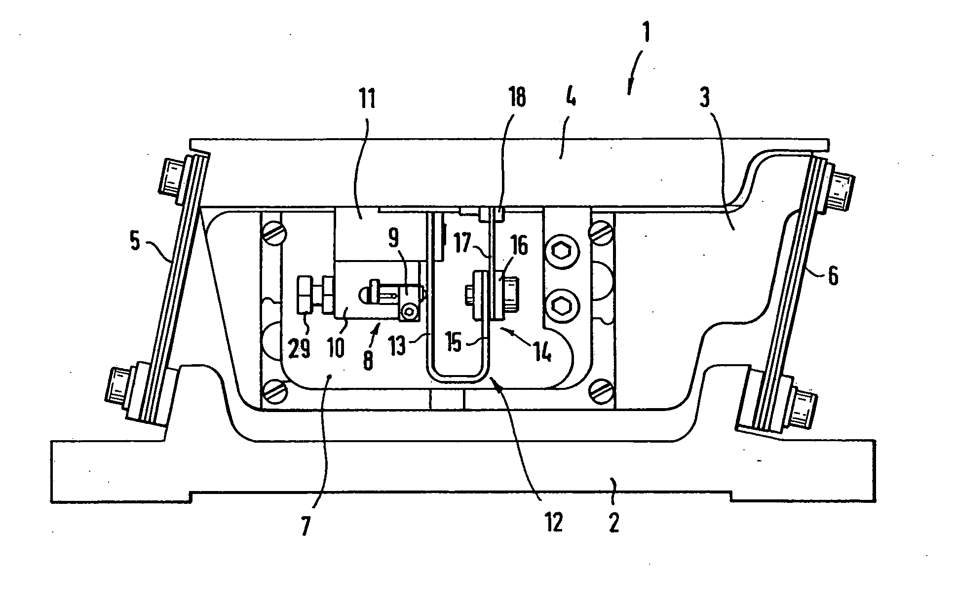
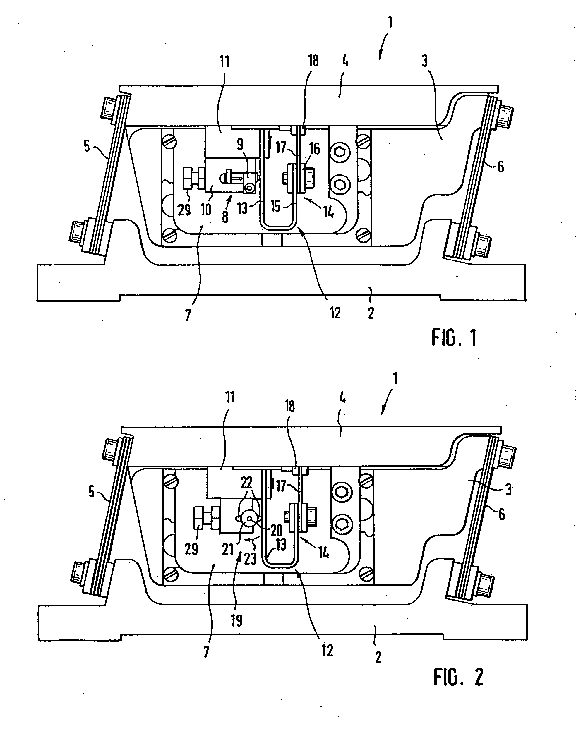
[0013]The drive unit usefully works directly against the spring element. I.e., the vibration of the drive unit is added directly to the spring element, where it is correspondingly amplified. This leads to efficient vibration propagation. The spring element itself is preferably a bent
leaf spring that is particularly usefully in a U-shape. This U-shape, with two lateral legs that are vertical when installed, and with one transverse leg that connects these two lateral legs, is particularly useful in terms of the linear movement of the weights, that is, for the linear travel.
[0014]Another advantageous embodiment of the invention provides that the stiffness of the spring element, in particular of the
leaf spring, varies across its length. This makes it possible to be able to adjust a wide vibrating amplitude in certain spring areas, i.e. in this area the spring vibrates somewhat farther, which is useful for the amplification. In accordance with a first embodiment of the invention, the bent leaf springs can be narrower in the area of the spring leg that faces away from the drive unit. I.e., the geometry of the spring changes on the spring leg that is not directly coupled to the drive unit or for instance is not indirectly coupled to the drive unit via an intermediate unit. For instance, the width of the spring leg decreases in this area to half the width of the other spring leg. However, it would also be conceivable to provide corresponding passages or the like on the spring leg. Alternative to the integral embodiment of the bent leaf spring having varying leg widths, the spring leg facing away from the drive unit can also be embodied in two parts and can comprise a first leg segment and a second leg segment that is thinner and that is joined thereto. In this embodiment of the invention, then, the leaf spring has two parts. A first spring part, which is itself already essentially U-shaped, has a first thickness, for instance approx. 1.5 mm, while a second spring part, which is joined to the one free spring leg, that is, to the spring leg that is not directly or indirectly activated by the drive unit, has a second thickness of for instance 0.8 mm. These two spring or leg parts are joined to one another via a suitable connection piece. Via such a change in the vibration properties of the spring that results from different material thicknesses it is also possible to attain a sharp increase in vibrating amplitude, which can also be adjusted as needed by appropriately selecting the leaf spring parts used (different thicknesses, widths, materials).
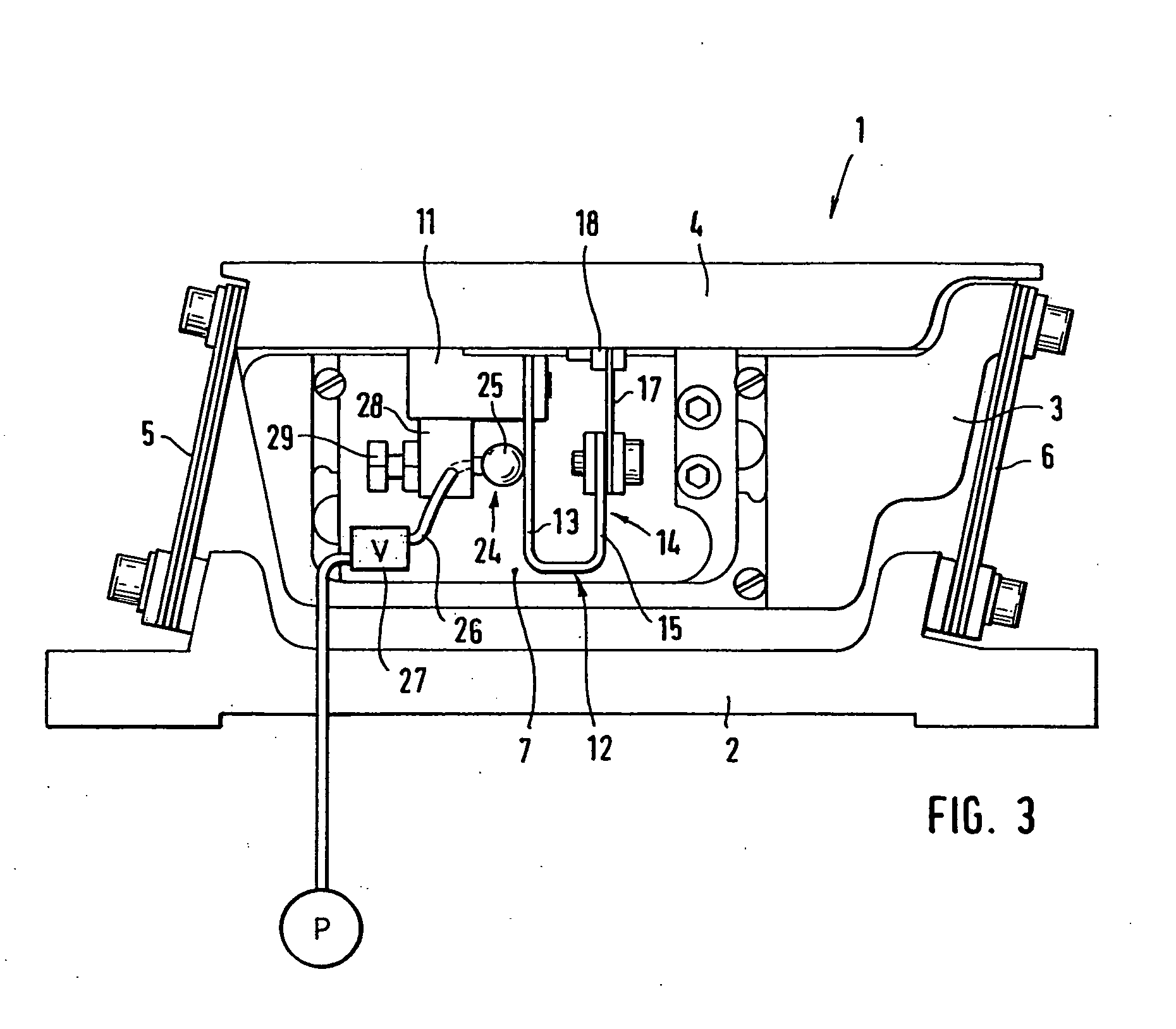
[0017]In addition, the larger
piston can be created by means of a membrane that limits a fluid reservoir and that can be moved directly or indirectly via the drive unit. The membrane is moved via the drive unit, this acting on the fluid, e.g. an oil. The fluid reservoir has a segment with a smaller
diameter into which the fluid is pressed, the path traveled there being much longer than the membrane is moved. Provided in this area is the second
piston, which is moved via the moving column of fluid and thus moves the other weight. If the membrane is unloaded, the second
piston can press the column of fluid back, creating vibration, the vibrating amplitude being significantly increased via the
transmission ratio, which is semi-hydraulic.

