
Inkjet image forming apparatus

a technology of image forming and inkjet, which is applied in the direction of inking apparatus, printing apparatus, other printing apparatus, etc., can solve the problems of severe deterioration of image quality in a whole image, create line displacement in an outputted image, etc., and achieve the effect of minimizing deterioration of image quality and preventing line displacemen

Inactive Publication Date: 2009-02-05
S PRINTING SOLUTION CO LTD
View PDF12 Cites 10 Cited by
  • Summary
  • Abstract
  • Description
  • Claims
  • Application Information

AI Technical Summary

Benefits of technology

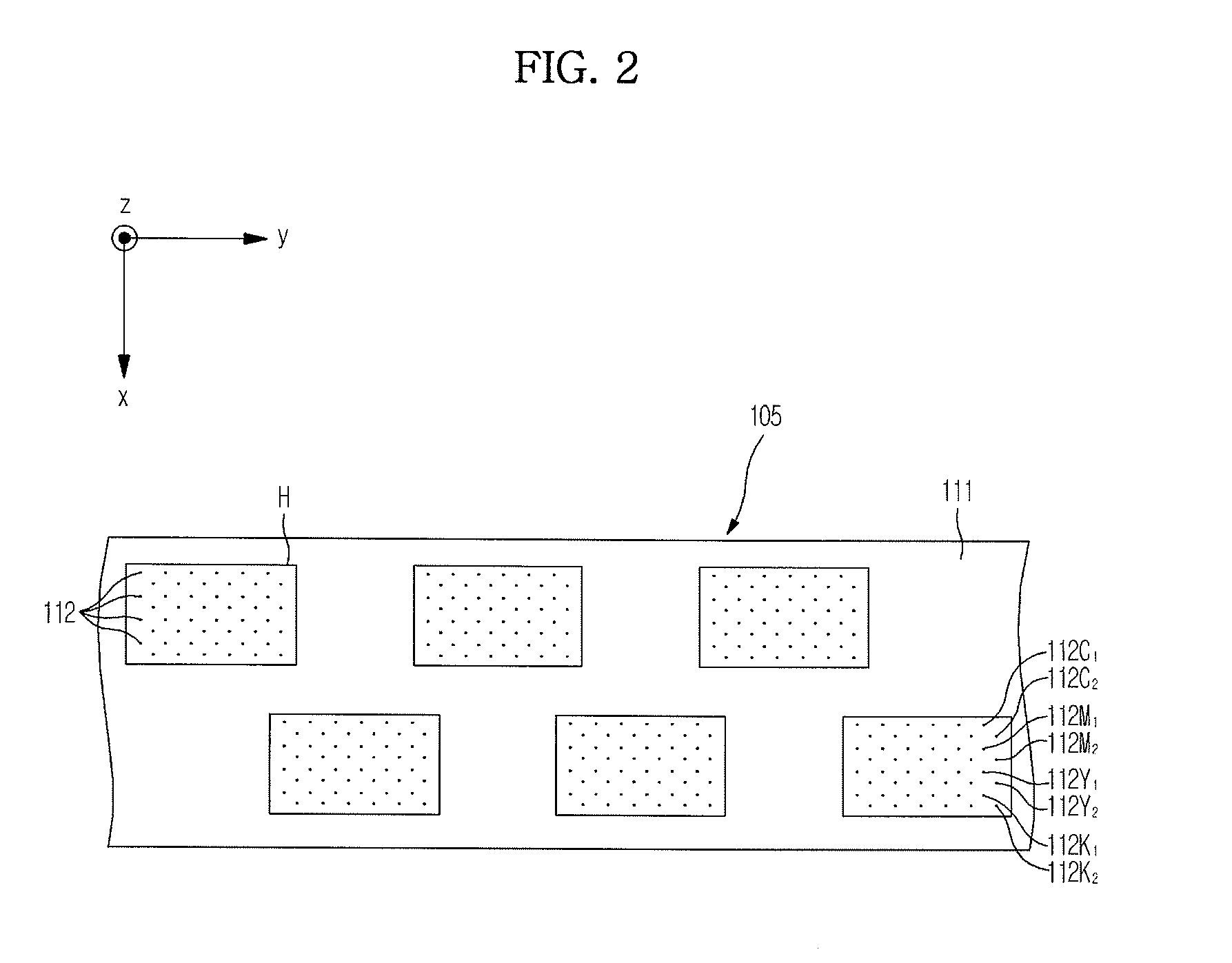
[0009]The present general inventive concept provides an inkjet image forming apparatus capable of minimizing deterioration of image quality by preventing line displacement in an outputted image, though a plurality of head chips mounted to a print head including a head chip having an erroneous gap between nozzle rows for each color.
[0020]The foregoing and / or other aspects and utilities of the present general inventive concept may also be achieved by providing an inkjet image forming device including a plurality of printing medium conveying parts to convey a printing medium, a print head including a plurality of head chips each having a plurality of rows of nozzles to print an image on the printing medium, and a control unit to receive from an external device position information of a head chip of the print head having a normal gap formed between two adjacent rows of at least one of the plurality of head chips and of a head chip of the print head having an erroneous gap formed between the two adjacent rows of at least one of the plurality of head chips, and to control the head chip having the normal formed gap and the head chip having the erroneous formed gap to perform a printing operation in a first mode for the head chip having the normal formed gap and in a second mode for the head chip having the erroneous formed gap by adjusting the printing timing of the two adjacent rows of nozzles.

Problems solved by technology

However, a dot gap between an odd row of nozzles and an even row of nozzles may be shortened or lengthened more than a normal gap by various factors in a semiconductor process of manufacturing a head chip of a print head, which creates line displacement in an outputted image.
However, in a case of an array type inkjet image forming apparatus which includes a plurality of head chips, line displacement caused by the respective head chips creates a problem of severe deterioration of image quality in a whole image.

Method used


Image

  • Inkjet image forming apparatus
  • Inkjet image forming apparatus
  • Inkjet image forming apparatus

Examples


Embodiment Construction

[0040]Reference will now be made in detail to exemplary embodiments of the present general inventive concept, examples of which are illustrated in the accompanying drawings, wherein like reference numerals refer to like elements throughout. The embodiments are described below to explain the present general inventive concept by referring to the figures.

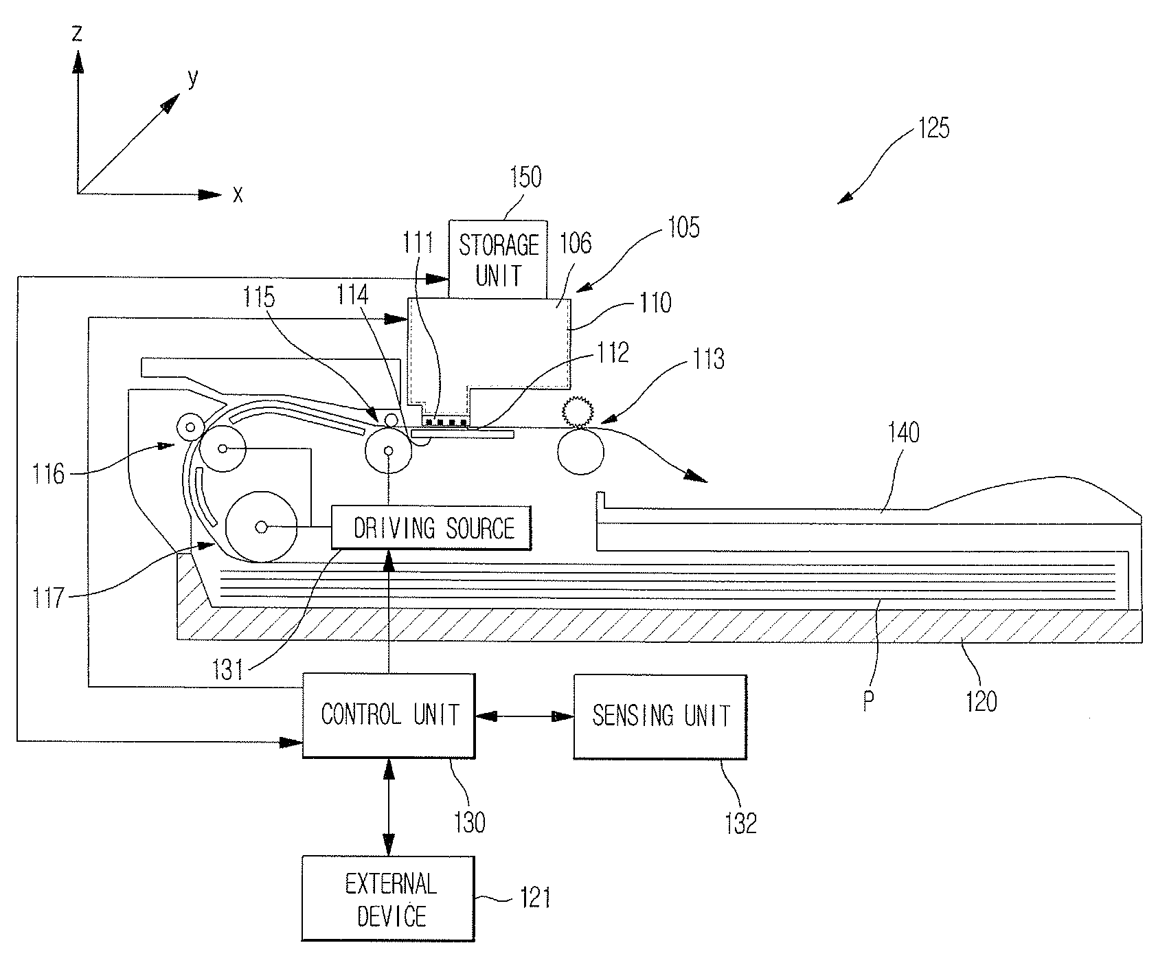
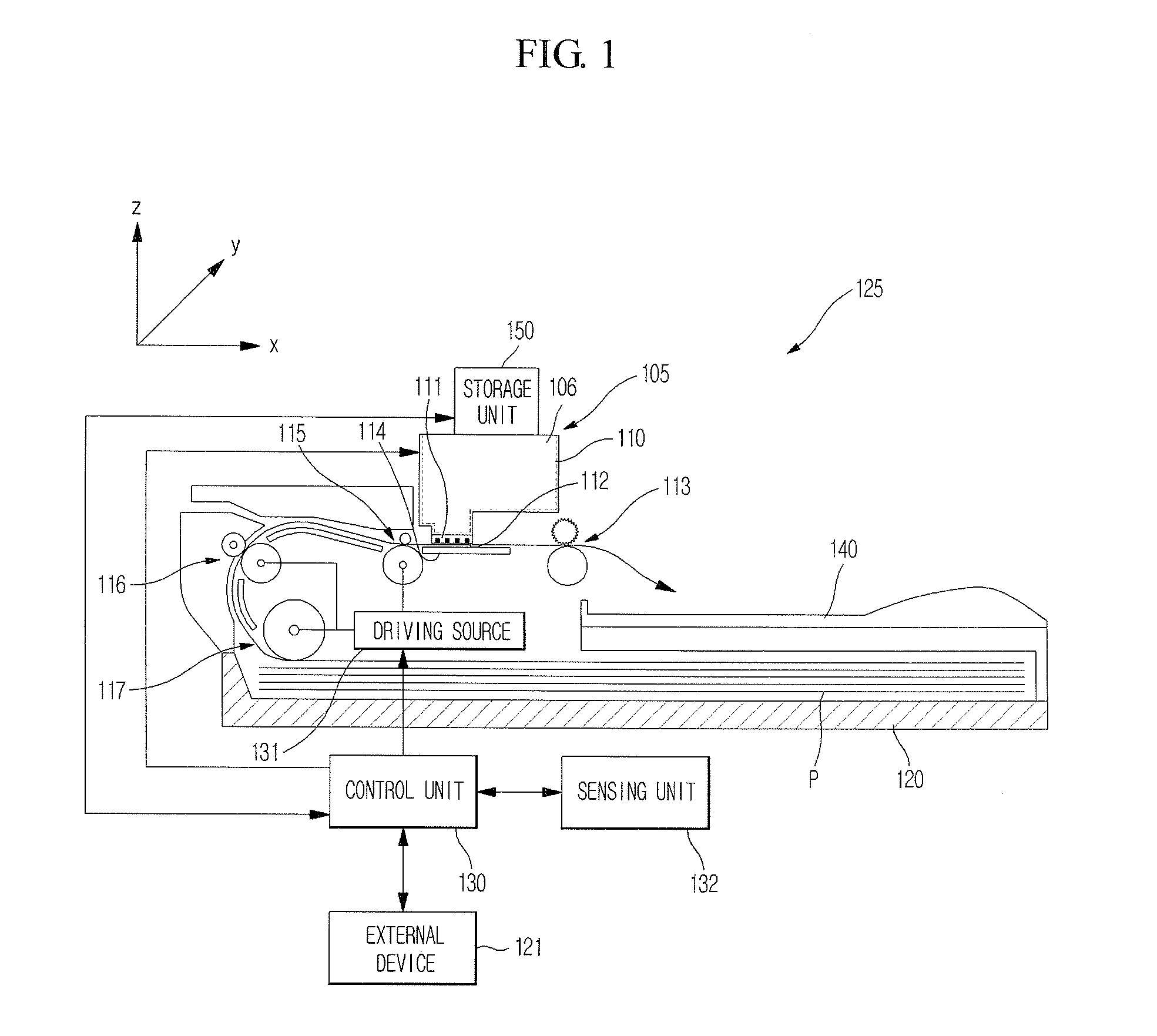
[0041]FIG. 1 is a view schematically illustrating an inkjet image forming apparatus according to the present general inventive concept. Referring to FIG. 1, an inkjet image forming apparatus 125 includes a paper feeding cassette 120, a print head unit 105 having an ink cartridge 106 with a housing 110, a supporting member 114 provided to oppose the print head unit 105, a sensing unit 132 to sense whether nozzles of a nozzle unit 112 malfunction, printing medium conveying parts 117, 116, 115 and 113 to convey a printing medium P in a first direction (x-direction), and a loading part 140 on which the discharged printing medium P is loade...


PUM


Abstract

An inkjet image forming apparatus is disclosed. A print head is provided having a plurality of head chips having nozzles arranged in at least two rows for each color. A storage unit stores position information of a head chip having a normal formed gap (which is in an integer multiple relationship having a resolution of, e.g., 9″ / 1200 or 10″ / 1200) between a first row of nozzles and a second row of nozzles of the at least two rows of nozzles, position information of a head chip having an erroneous formed gap (which is not in an integer multiple relationship having a resolution of, e.g., 8.5″ / 1200 or 9.5″ / 1200) between the first row of nozzles and the second row of nozzles, and gap information. A control unit controls the head chip having the normal formed gap according to a first mode, by which printing data of the first row of nozzles and the second row of nozzles for each line are simultaneously printed to have a basic vertical resolution, and to control the head chip having the erroneous formed gap according to a second mode, by which the printing data of the first row of nozzles and the second row of nozzles for each line are alternately printed to have a double basic vertical resolution.

Description

CROSS-REFERENCE TO RELATED APPLICATIONS[0001]This application claims the benefit and priority under 35 U.S.C. § 119(a) of Korean Patent Application No. 2007-0078256, filed on Aug. 3, 2007 in the Korean Intellectual Property Office, the disclosure of which is incorporated herein by reference in its entirety.BACKGROUND OF THE INVENTION[0002]1. Field of the Invention[0003]The present general inventive concept relates to an inkjet image forming apparatus, and more particularly, to an inkjet image forming apparatus capable of minimizing deterioration of image quality by preventing line displacement, though a plurality of head chips mounted to a print head in a two-row arrangement structure including a head chip having an erroneous gap between nozzle rows.[0004]2. Description of the Related Art[0005]An inkjet image forming apparatus refers to an apparatus that forms an image by ejecting ink to a printing medium from an inkjet head which is spaced apart from the printing medium and recipro...

Claims


Application Information

Patent Timeline
IPC IPC(8): B41J29/38
CPCB41J2/2139B41J2202/19B41J2002/14362B41J2/2142B41J2/145B41J2/135B41J2/07
Inventor HAN, CHUN KU
Owner S PRINTING SOLUTION CO LTD
Learn More