
Organic thin-film transistor manufacturing method, organic thin-film transistor, and organic thin-film transistor sheet

a technology of organic thin film transistors and manufacturing methods, applied in thermoelectric devices, non-linear optics, instruments, etc., can solve the problems of lowering the transistor properties, reducing the manufacturing cost or running cost, and increasing the size of the display panel. , to achieve the effect of minimizing deterioration, minimizing deterioration, and minimizing deterioration with tim

Inactive Publication Date: 2005-07-21
HIRAI KATSURA
View PDF10 Cites 42 Cited by
  • Summary
  • Abstract
  • Description
  • Claims
  • Application Information

AI Technical Summary

Benefits of technology

"The present invention aims to provide a method for manufacturing organic thin-film transistors that minimizes deterioration during the manufacturing process and with time or due to folding of the transistor properties. Additionally, the invention provides an organic thin-film transistor and an organic thin-film transistor sheet that minimize deterioration with time or due to folding of the transistor properties."

Problems solved by technology

In the manufacture of a flat panel display employing such a TFT, a photolithography step with high precision is required in addition to a thin layer forming step requiring a vacuum line carrying out a CVD method or a sputtering method or a high temperature treatment step, which results in great increase of manufacturing cost or running cost.
Recent demand for a large-sized display panel further increases those costs described above.
However, an organic thin-film transistor, when allowed to stand in air, deteriorates, resulting in lowering of transistor properties.
Further, an organic thin-film transistor, when manufactured by a process comprising forming an organic semiconductor layer, followed by coating of a light sensitive resin layer, and development of the light sensitive resin layer air, results in deterioration of transistor properties due to a solvent used for coating or components contained in a developer used for development.
Therefore, the former has problem in that properties as a transistor deteriorate due to folding, or due to light.

Method used


Image

  • Organic thin-film transistor manufacturing method, organic thin-film transistor, and organic thin-film transistor sheet
  • Organic thin-film transistor manufacturing method, organic thin-film transistor, and organic thin-film transistor sheet
  • Organic thin-film transistor manufacturing method, organic thin-film transistor, and organic thin-film transistor sheet

Examples


example 1

Preparation of Organic Thin-Film Transistor Samples 1 through 9

(1) Preparation of Organic Thin-Film Transistor Sample 1

Preparation of Substrate

[0178] A mixture of 3.04 g (20 mmol) of tetramethoxysilane, 1.52 g of methylene chloride, and 1.52 g of ethanol was mixed with 0.72 g of an aqueous 0.5% by weight nitric acid solution for hydrolysis, and stirred at room temperature for one hour. A solution in which 1.60 g of diacetylcellulose L50 (produced by Daicel Co., Ltd.) was dissolved in a mixed solvent of 5.3 g of ethanol and 60.9 g of methyl acetate was added to the resulting mixture above, and stirred for one hour to obtain a dope. The resulting dope was cast on a moving gum belt through a doctor blade with a gap width of 800 μm, and dried at 120° C. for 30 minutes to obtain a substrate 1 with a thickness of 200 μm. The substrate 1 had a Tg of 226° C., which was obtained by dynamic viscoelastic measurement.

[0179] The surface of substrate 1 was corona discharged at 50 W / m2 / min and...

example 2

Evaluation of Organic Thin-Film Transistor Samples 1 Through 10

[0207] The organic thin-film transistor sample 1 and organic thin-film transistor samples 5 through 10 exhibited good working property as a p-channel enhancement type FET. With respect to the organic thin-film transistor samples 1 through 10, carrier mobility (cm2 / V sec), and an ON / OFF ratio (a drain current ratio when a drain bias was −50 V and a gate bias was −50V and 0 V) were determined from a saturation region of I-V characteristic.

[0208] Further, after the organic thin-film transistor samples 1 through 10 were stored in an atmosphere for one month, the carrier mobility and the ON / OFF ratio thereof were determined.

[0209] Each of the organic thin-film transistor samples 1 through 10 was folded while the substrate side of each sample contacted a stainless steel shaft with an R of 10 mm, and then carrier mobility thereof was determined. The results are shown in Table 1.

TABLE 1Immediately afterAfter one monthAfterp...

example 3

Preparation of Organic Thin-Film Transistor Sample 11 and its Evaluation

[0211] Organic thin-film transistor sample 11 was prepared in the same manner as organic thin-film transistor sample 1, except that a mixture layer of polyvinyl alcohol and carbon black (=8:2 by weight) was used as an organic semiconductor layer protective layer instead of the organic semiconductor layer protective layer of polyvinyl alcohol. The resulting mixture layer of polyvinyl alcohol and carbon black had an average light transmittance at visible wavelength regions of 0.1%.

[0212] The organic thin-film transistor sample 10 provided the same good FET property as the organic thin-film transistor sample 1. When the sample 11 immediately after prepared was exposed to light of 500 cd through a tungsten lamp, properties thereof were not changed.


PUM

PropertyMeasurementUnit
light transmittanceaaaaaaaaaa
wavelengthaaaaaaaaaa

Abstract

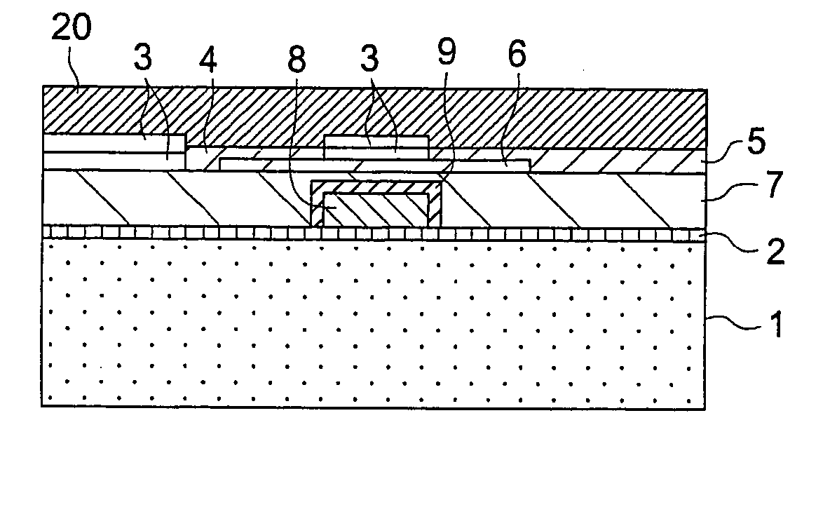
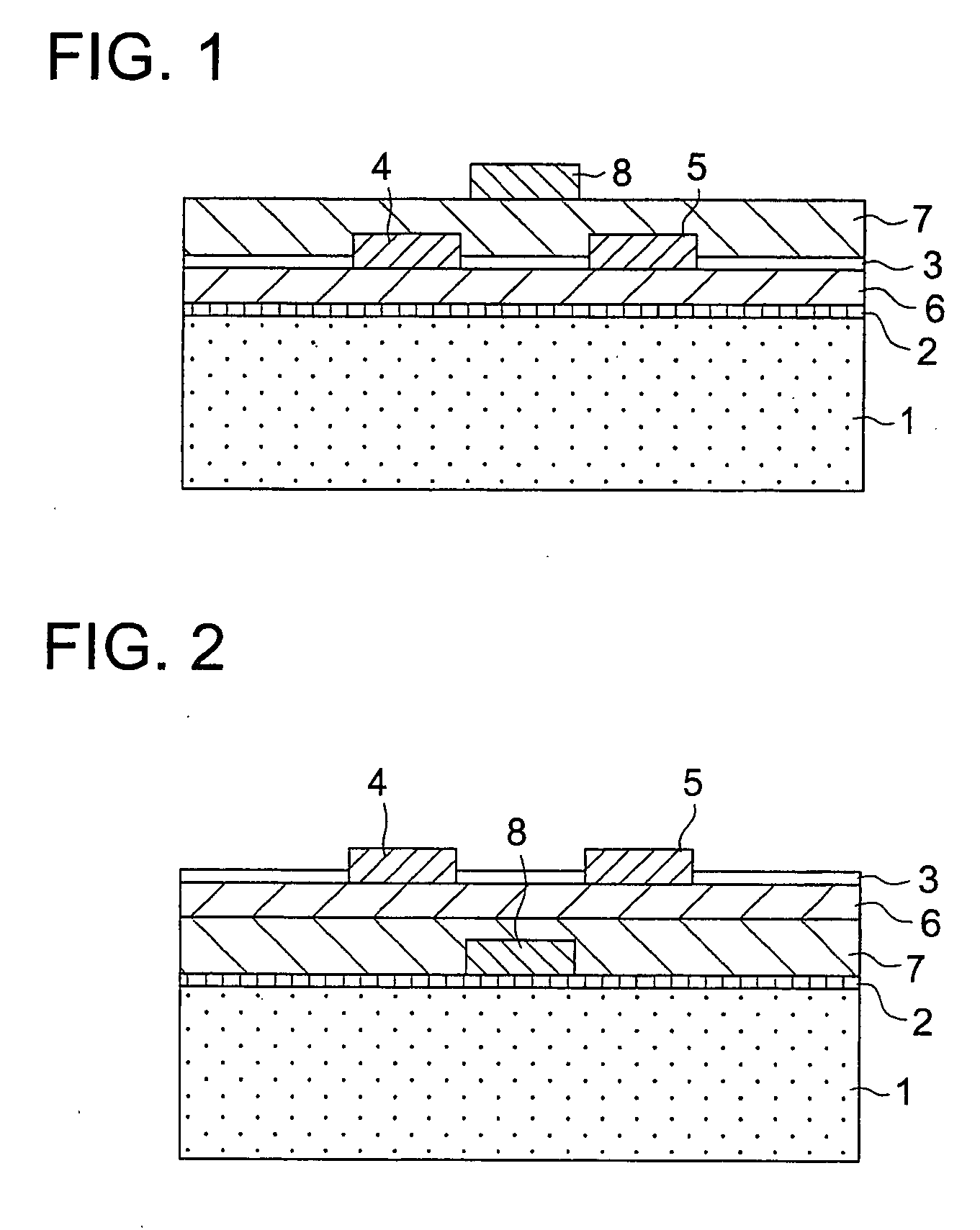
An organic thin-film transistor manufacturing method and an organic thin-film transistor manufactured by the method are disclosed, the method comprising the steps of a) forming a gate electrode on a substrate, b) forming a gate insulating layer on the substrate, c) forming an organic semiconductor layer on the substrate, d) forming an organic semiconductor layer protective layer on the organic semiconductor layer, e) removing a part of the organic semiconductor layer protective layer, and f) forming a source electrode and a drain electrode at portions where the organic semiconductor layer protective layer has been removed, so that the source electrode and drain electrode contacts the organic semiconductor layer.

Description

CROSS-REFERENCE TO RELATED APPLICATION [0001] The present application is a divisional application of U.S. patent application Ser. No. 10 / 742,194, filed on Dec. 19, 2003, the entire contents of which are incorporated herein by reference. The Ser. No. 10 / 742,194 application claimed the benefit of the date of the earlier filed Japanese Patent Application No. JP 2002-376793 filed Dec. 26, 2002, and priority to JP 2002-376793 filed Dec. 26, 2002 is also claimed in the present divisional application.FIELD OF THE INVENTION [0002] The present invention relates to an organic thin-film transistor manufacturing method, an organic thin-film transistor manufactured by the method, an organic thin-film transistor, and an organic thin-film transistor sheet. BACKGROUND OF THE INVENTION [0003] With the spread of information terminals, there are increasing demands for a flat panel display that serves as a display for a computer. Further, with development of the information technology, there has been i...

Claims


Application Information

Patent Timeline
Patent Type & Authority Applications(United States)
IPC IPC(8): G02F1/1368H01L27/28H01L51/05H01L51/10H01L51/30H01L51/40H10N10/856
CPCG02F1/1368H01L51/107H01L27/28H01L27/283H01L51/0037H01L51/0052H01L51/0055H01L51/0512H01L51/0516H01L51/0525H01L51/0529H01L51/0533H01L51/0537H01L51/0541H01L51/0545H01L51/10H01L51/102G02F2202/02H10K19/10H10K85/1135H10K85/623H10K85/615H10K10/462H10K10/468H10K10/472H10K10/474H10K10/478H10K10/476H10K10/464H10K10/82H10K10/88H10K10/466H10K10/80H10K19/00
Inventor HIRAI, KATSURA
Owner HIRAI KATSURA
Learn More