Indexable insert

a technology of indexable inserts and inserts, which is applied in the direction of cutting inserts, manufacturing tools, shaping cutters, etc., can solve the problems of deteriorating the processing ability of chips, crater abrasion in contact regions, and serious damage, so as to enhance the protection effect of the first ridge is enhanced, and the resistive state is low

Active Publication Date: 2009-09-10
SUMITOMO ELECTRIC HARDMETAL CORP
View PDF11 Cites 41 Cited by
  • Summary
  • Abstract
  • Description
  • Claims
  • Application Information

AI Technical Summary

Benefits of technology

[0016]In the insert according to this invention, a chip is processed mainly by the first ridge not only during small-depth cutting, but also during large-depth cutting. The second ridge assists the first ridge during large-depth cutting so as to enhance the protection effect of the first ridge. Specifically, since the second ridge is continuously formed, a chip formed during large-depth cutting is guided along the second ridge, thereby preventing the chip from hitting against the first ridge. Because the height of the second ridge is lower than that of the first ridge, a chip guided by the second ridge subsequently comes into contact with the first ridge. However, since the motion energy of the chip is already attenuated and the load applied to the region of the first ridge in contact with the chip is thus alleviated as compared to when the chip directly hits the first ridge, the protection effect of the first ridge is enhanced.
[0017]Since the second ridge is convex-curved, the direction in which a chip is removed while being curled sideways during large-depth cutting is aligned with the curved direction of the second ridge. Therefore, the chip can be removed in a low resistive state. Since this reduces the load on the second ridge, damages to the second ridge rarely occur, thereby enhancing the durability of the first and second ridges. Accordingly, satisfactory chip processability can be maintained over a longer period of time by these ridges, as compared to that of a product of the related art.
[0018]As mentioned above, in the insert that further includes the flat breaker base surrounded by the first ridge, the two second ridges, and the nose cutting-edge, the length of the breaker base in the extending direction of the bisecting line of the apex angle of the nose may be set to 30% to 70% of the distance between the apex of the nose and the protruding edge of the top surface of the first ridge, and the depth of the breaker base measured from the cutting edge may be set within a range between 0.03 mm and 0.15 mm. In this case, the chip also comes into contact with the breaker base. Thus, the energy of the chip when it reaches the first ridge is further reduced, thereby further enhancing the effect of alleviating the load on the first ridge as well as the effect of minimizing damages to the first ridge.
[0019]Furthermore, in the insert in which the rising surface of the first ridge is defined by a concave-curved slope, the contact area between the first ridge and the chip is increased, thereby further enhancing the effect of alleviating the load on the first ridge.

Problems solved by technology

In the case of a high cutting speed or a large feed, the load applied to the contact regions between the chip 20 and the insert is large, leading to crater abrasion in the contact regions due to a temperature increase or to serious damages caused as a result of detachment of a coating from the insert.
However, increasing the length between the cutting edge and the breaker projection may deteriorate the chip processability.
This may result in deterioration of the chip processability at an early stage.
However, like the structure disclosed in Japanese Patent No. 3607288, this structure also lacks attention to the protection of the insert.
Therefore, the regions of the insert that are in contact with the chip 20 are abraded intensively, leading to chipping of the cutting edge and to reduced chip process ability.

Method used


Image

  • Indexable insert
  • Indexable insert
  • Indexable insert

Examples


Embodiment Construction

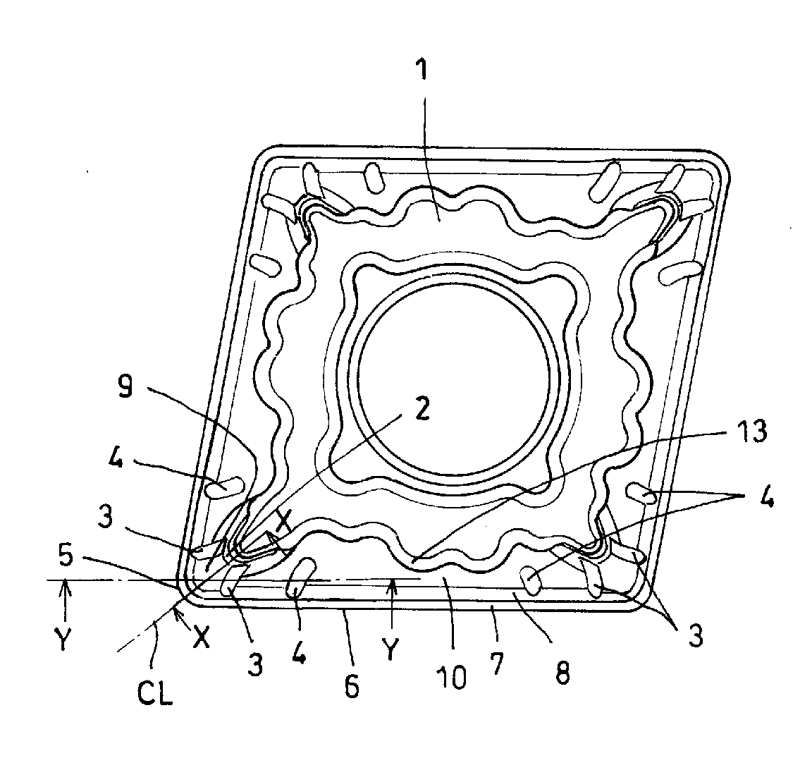
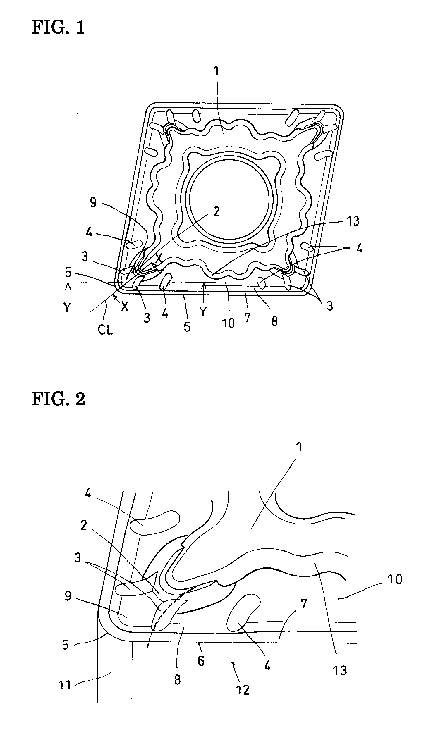
[0034]An indexable insert according to an embodiment the present invention will be described below with reference to FIGS. 1 to 10B. FIG. 1 is a plan view of a rake face of a diamond-shaped insert according to this invention, as viewed from above. FIG. 2 is a perspective view of one of acute corners of the insert shown in FIG. 1. This insert has a flat boss surface 1 at a central section on the top face thereof, two acute corners, and two obtuse corners. At each acute corner, the rake face has thereon a single first ridge 2 and a plurality of second ridges 3, and likewise, at each obtuse corner, the rake face has thereon a single first ridge 2 and a plurality of second ridges 3. These first ridges 2 and the second ridges 3 are characteristic features of this invention. The insert also has third ridges 4 at positions separated from the second ridges 3 by a predetermined distance. Although the first ridges 2 and the second ridges 3 in the obtuse corners have the same configuration as ...


PUM

PropertyMeasurementUnit
depthaaaaaaaaaa
depthaaaaaaaaaa
cutting depthaaaaaaaaaa

Abstract

An indexable insert has a rake face on which a first ridge (2) and a second ridge (3) are provided. The first ridge (2) protrudes from a boss surface (1) towards a nose, and the second ridge (3) extends continuously from the first ridge (2) to a slope (8) connected to a cutting-edge land (7) of a linear cutting edge (6). The second ridge (3) has a height lower than that of the first ridge (2) and is convex-curved towards a bisecting line (CL) of an apex angle of the nose in plan view, thereby achieving both enhanced chip processability and reduction of load received when raking a chip.

Description

BACKGROUND OF THE INVENTION[0001]1. Field of the Invention[0002]The present invention relates to indexable inserts used for turning. In particular, the present invention relates to an indexable insert that provides enhanced durability of a breaker projection while it maintains favorable chip processability so as to minimize deterioration of the chip processability at an early stage.[0003]2. Description of the Related Art[0004]A known indexable insert (sometimes simply referred to as an “insert” hereinafter) for turning, which is used by being attached to a tool holder, is provided with chip breakers on a rake face of the insert to enhance chip processability. The function of a chip breaker is to cut a chip formed during turning to an appropriate length so as to separate the chip from the workpiece and the cutting tool. Chip breakers having various shapes have been proposed, including those disclosed in Japanese Patent No. 3607288 and Japanese Unexamined Patent Application Publicatio...

Claims


Application Information

Patent Timeline
Patent Type & Authority Applications(United States)
IPC IPC(8): B23B27/16B23B27/22
CPCB23B27/143B23B2200/081Y10T407/245Y10T407/23Y10T407/24Y10T407/235
Inventor IYORI, HIDETOKIMURA, NORIHIDETSUDA, KEIICHI
Owner SUMITOMO ELECTRIC HARDMETAL CORP
Why Eureka
Try Eureka