Image scanning apparatus

Active Publication Date: 2009-02-05
SEIKO EPSON CORP
View PDF4 Cites 1 Cited by
  • Summary
  • Abstract
  • Description
  • Claims
  • Application Information

AI Technical Summary

Benefits of technology

[0012]In this arrangement, since increase in extent of inclination of the supporting shaft caused by the creep is restrained by the restraining member, the supporting shaft is prevented from significantly inclining. In other words, even with the supporting shaft which has a tendency to incline by being integrated with the one of the frame member, one of the rotating bodies wound by the belt therearound with tension is adequately supported.
[0015]Preferably, the one frame member includes a bottom frame and a side frame extending upright at one end in the direction along the direction of contact of the bottom frame, and the bearing unit includes a rib projecting from the bottom frame and extending from an outer peripheral surface of the bearing unit along the direction of contact so as to be in contact with the bottom frame and the side frame. In this arrangement, the strength of the bearing unit against the load exerted on the bearing unit when the contact surface is brought into contact with the distal end portion is improved.
[0016]Preferably, the bearing unit includes a rib extending from the inner peripheral surface on the side of the contact surface to a portion thereof on the opposite side from the contact surface in terms of the direction of contact. In this configuration, the strength of the bearing unit against the load exerted on the bearing unit when the contact surface is brought into contact with the distal end portion is improved.
[0017]Preferably, the pair of rotating bodies are a pair of pulleys, and the supporting shaft rotatably supports one of the pair of pulleys, and the bearing unit prevents the pulley from coming apart from the supporting shaft. In this configuration, the number of components of the image scanning apparatus is smaller in comparison with the configuration in which a restraining member for preventing the pulley from coming apart is separately provided, so that the image scanning apparatus is further simplified.

Problems solved by technology

However, integration of the supporting shaft with the one of the frame member fixes the position of the supporting shaft, and hence the supporting shaft has a tendency to incline due to a shaft load exerted on the supporting shaft by the belt wound around the pair of rotating bodies with tension.
In addition, when the shaft load is continuously exerted on the supporting shaft, the extent of inclination of the supporting shaft is increased due to so-called creep.
When the extent of inclination is remarkably increased, the image scanning apparatus will suffer from difficulty in scanning the image adequately.

Method used


Image

  • Image scanning apparatus
  • Image scanning apparatus
  • Image scanning apparatus

Examples


Embodiment Construction

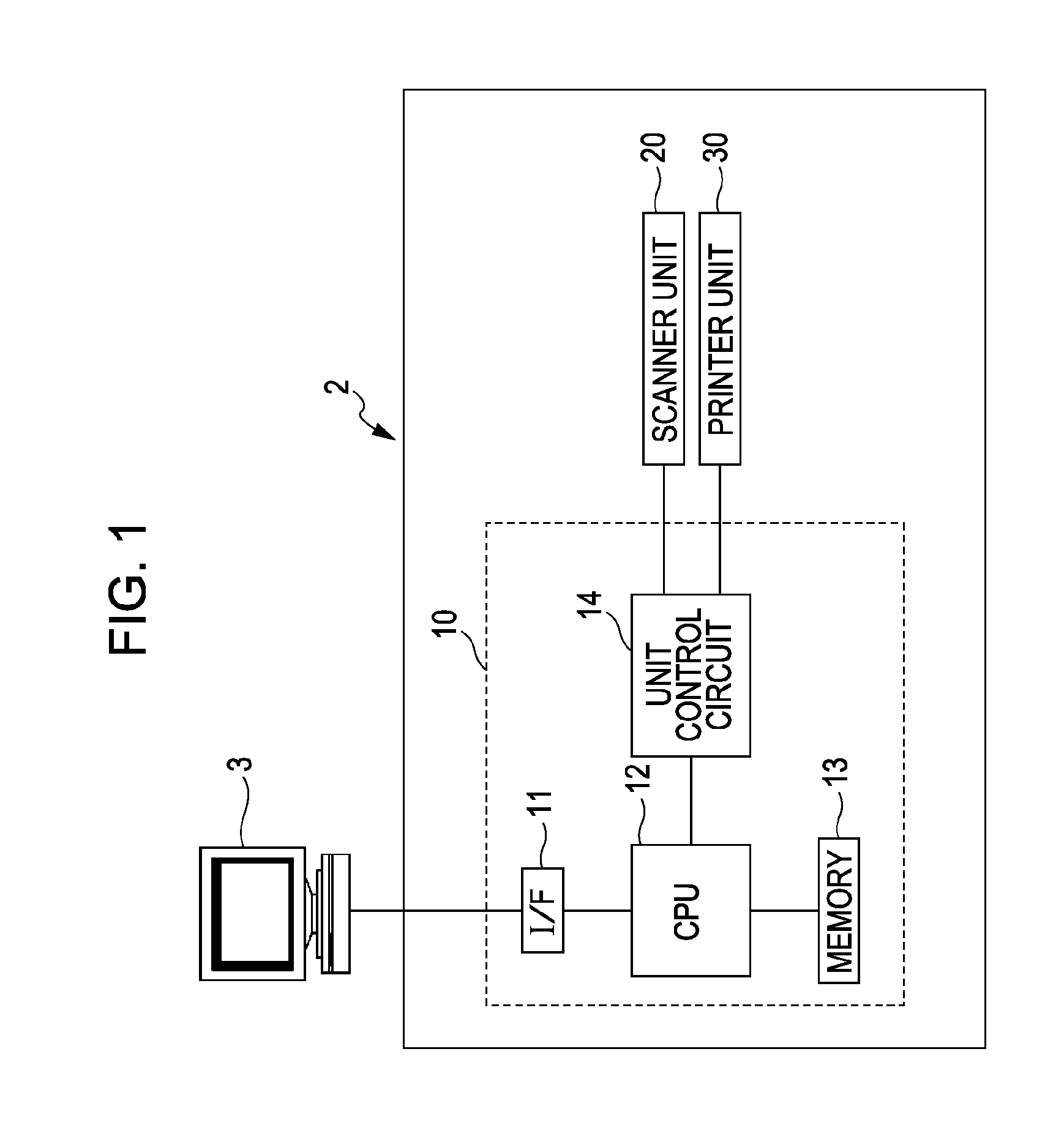
[0031]Referring now to FIG. 1, a multifunction apparatus 2 as an example of an image scanning apparatus will be described. FIG. 1 is a block diagram of the multifunction apparatus 2.

[0032]The multifunction apparatus 2 has a scanner function for scanning an image from a document; a printer function for printing the image on a printing sheet on the basis of a print data from an external computer 3, and a copying function for printing the image scanned from the document on the printing sheet.

[0033]The multifunction apparatus 2 includes a controller 10, a scanner unit 20 and a printer unit 30 as shown in FIG. 1. The controller 10 controls the multifunction apparatus 2, and includes an interface 11 (indicated as I / F in FIG. 1), a CPU 12, a memory 13 and a unit control circuit 14. The CPU 12 controls the respective units (that is, the scanner unit 20 and the printer unit 30) by the unit control circuit 14 according to programs stored in the memory 13.

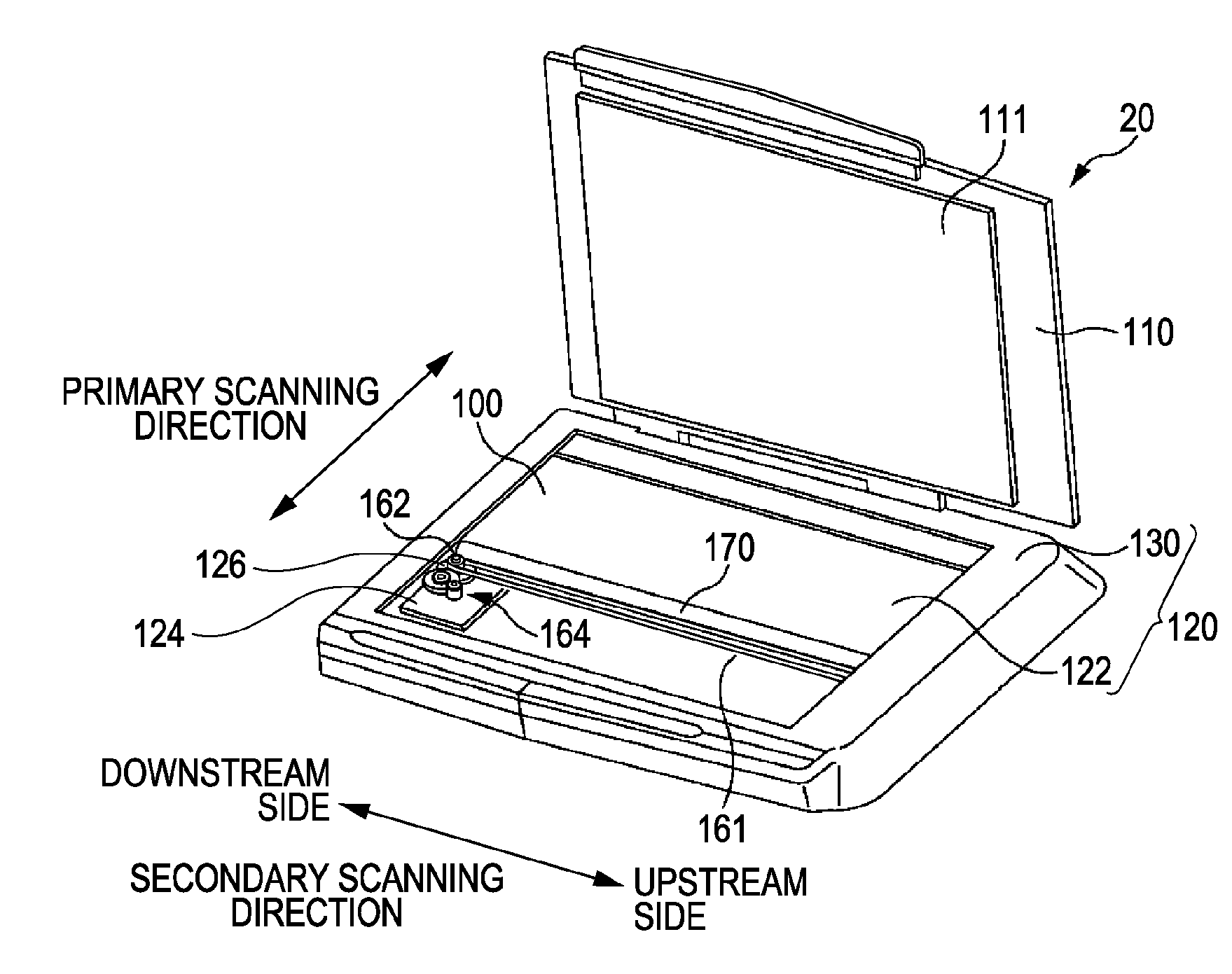
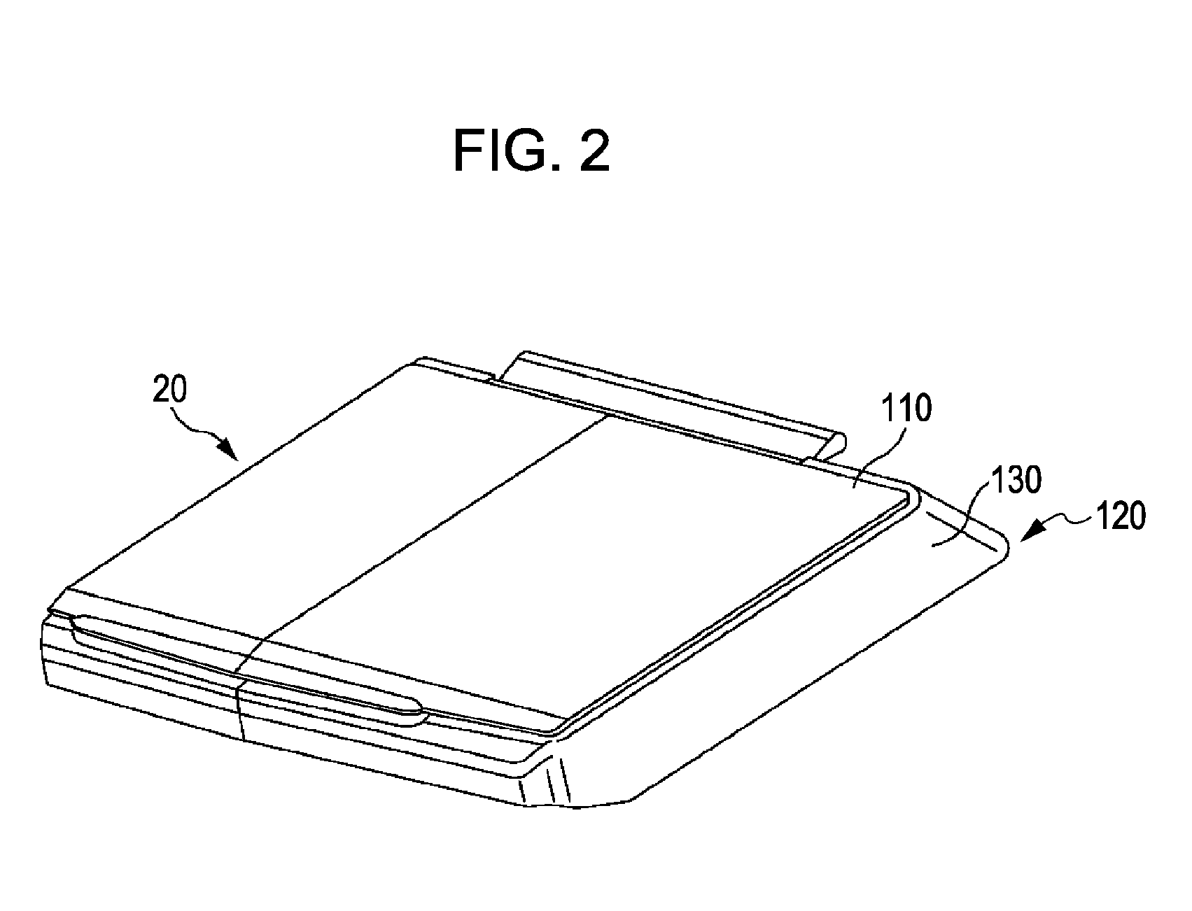
[0034]The scanner unit 20 includes a g...


PUM


Abstract

An image scanning apparatus includes an endless belt; a pair of rotating bodies being adapted to wind the belt therearound with tension and rotating for rotating the belt; an image scanning unit which moves in association with the rotation of the belt in a state of being fixed to the belt for scanning an image from a document; a pair of frame members connected to each other; a supporting shaft integrated with one of the frame members for rotatably supporting one of the rotating bodies; and a restraining member provided on the other frame member for restraining inclination of the supporting shaft caused by a shaft load applied to the supporting shaft by the belt being wounded around the pair of rotating members with tension.

Description

BACKGROUND[0001]1. Technical Field[0002]The present invention relates to an image scanning apparatus.[0003]2. Related Art[0004]An image scanning apparatus including an endless belt, a pair of rotating bodies being adapted to wind the belt therearound with tension and rotating for rotating the belt, an image scanning unit for scanning image from a document, and a pair of frame members connected to each other is already known (see JP-A-2000-37921). The pair of rotating bodies are supported so as to be capable of rotating independently.[0005]An attempt is made to simplify the image scanning apparatus for reducing the cost of the same. As a measure for simplifying the image scanning apparatus, for example, integrating a supporting shaft for supporting one of the rotating bodies with one of the frame members to reduce the number of components of the image scanning apparatus is considered.[0006]However, integration of the supporting shaft with the one of the frame member fixes the positio...

Claims


Application Information

Patent Timeline
IPC IPC(8): H04N1/04
CPCH04N1/00559H04N1/1017H04N2201/0446H04N1/103H04N1/193H04N1/1026
Inventor AKAHANE, HISAYUKI
Owner SEIKO EPSON CORP
Why Eureka
Try Eureka