
Method of improving sensitivity of electric field sensor, storage apparatus including electric field sensor, and method of reproducing information of the storage apparatus

a technology of electric field sensor and sensitivity improvement, which is applied in the field of storage apparatus and reproducing information of storage apparatus, can solve the problems of limited recording density and increase recording density, and achieve the effect of improving the sensitivity of electric field sensor and improving read sensitivity

Inactive Publication Date: 2009-02-05
SAMSUNG ELECTRONICS CO LTD
View PDF4 Cites 3 Cited by
  • Summary
  • Abstract
  • Description
  • Claims
  • Application Information

AI Technical Summary

Benefits of technology

[0009]The present invention provides a method of improving the sensitivity of an electric field sensor, a storage apparatus having improved read sensitivity and a method of reproducing information of the storage apparatus.
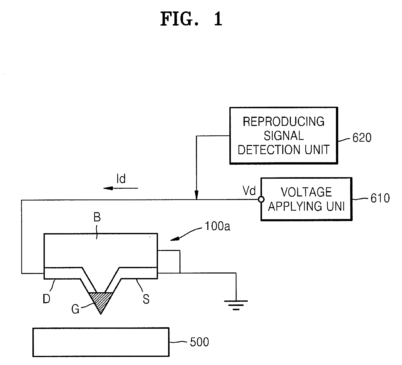
[0010]According to an aspect of the present invention, there is provided a method of improving the sensitivity of an electric field sensor including a source region, a drain region and a resistance region electrically connecting the source region to the drain region and having a resistance, which varies according to an intensity of an electric field, and detecting a change in an electric field by measuring a change in a drain current flowing through the resistance region, wherein the measuring a change in the drain current includes: passing the drain current through at least one negative resistor; and detecting a change in a voltage between the drain region and the at least one negative resistor.

Problems solved by technology

However, since it is difficult for the magnetic read / write head to form a strong localized magnetic field, the increase in recording density is limited.

Method used


Image

  • Method of improving sensitivity of electric field sensor, storage apparatus including electric field sensor, and method of reproducing information of the storage apparatus
  • Method of improving sensitivity of electric field sensor, storage apparatus including electric field sensor, and method of reproducing information of the storage apparatus
  • Method of improving sensitivity of electric field sensor, storage apparatus including electric field sensor, and method of reproducing information of the storage apparatus

Examples


Embodiment Construction

[0034]Hereinafter, a method of increasing the sensitivity of an electric field sensor, a storage apparatus having increased read sensitivity and a method of reproducing information of the storage apparatus will be described. In the drawings, the thickness of layers and region are exaggerated for clarity. The same reference numerals in the drawings denote the same element.

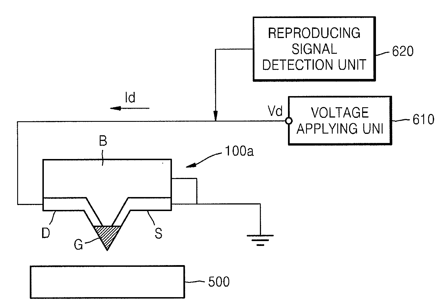
[0035]FIG. 1 is a structure view of a storage apparatus according to an exemplary embodiment of the present invention. The storage apparatus includes an electric field sensor 100a of a resistance probe type. A resistance region G, a source region S and a drain region D are disposed on a body B of the electric field sensor 100a, wherein the resistance region G is a region doped with low concentration, and the source region S and the drain region D may be disposed on either side of the resistance region G, and are each a region doped with high concentration. When the body B is a p type semiconductor, the resistance re...


PUM

PropertyMeasurementUnit
voltageaaaaaaaaaa
voltageaaaaaaaaaa
voltageaaaaaaaaaa

Abstract

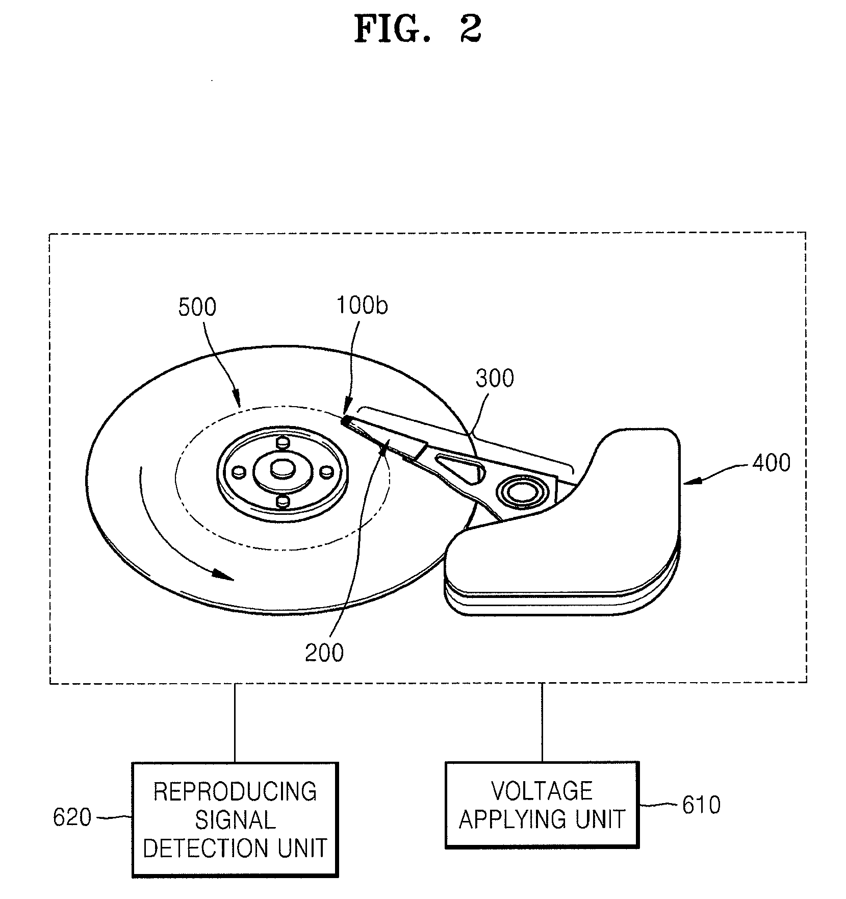
A storage apparatus includes a ferroelectric recording medium, an electric field sensor including a source region, a drain region and a resistance region electrically connecting the source region to the drain region and having a resistance, which varies according to an intensity of an electric field due to a polarization voltage of an electric domain of the recording medium, a voltage applying unit applying a drain voltage between the source region and the drain region, and a reproducing signal detection unit including at least one negative resistor installed in an electric circuit connecting the drain region to the voltage applying unit, and detecting a change in a voltage between the drain region and the at least one negative resistor.

Description

CROSS-REFERENCE TO RELATED PATENT APPLICATION[0001]This application claims priority from Korean Patent Application No. 10-2007-0076432, filed on Jul. 30, 2007, in the Korean Intellectual Property Office, the disclosure of which is incorporated herein in its entirety by reference.BACKGROUND OF THE INVENTION[0002]1. Field of the Invention[0003]The present invention relates to a storage apparatus and a method of reproducing information of the storage apparatus, and more particularly, to a storage apparatus and a method of reproducing information of the storage apparatus, in which information recorded in a ferroelectric recording medium is read using an electric field sensor.[0004]2. Description of the Related Art[0005]A Hard Disk Drive (HDD), which is a primary storage device of a computer, operates by spinning a data-recording medium and suspending a read / write head over the data-recording medium in order to read and write data. A conventional HDD normally uses a magnetic field to cre...

Claims


Application Information

Patent Timeline
Patent Type & Authority Applications(United States)
IPC IPC(8): G11B9/00
CPCB82Y10/00G11B9/1409G11B9/02G11B9/04G11B5/39G11B5/31
Inventor JEON, DAE-YOUNGMIN, DONG-KIKO, HYOUNG-SOOHONG, SEUNG-BUM
Owner SAMSUNG ELECTRONICS CO LTD
Learn More