IP telephony network using a configuration map for organizing sites in a tree-like hierarchy

a configuration map and site technology, applied in the field of ip telephony network using a configuration map for organizing sites in a tree-like hierarchy, can solve the problems of network inability to scale, network bottlenecks, time and resource consumption, etc., to achieve scalable and robust system, efficient and easy-to-use effects

Inactive Publication Date: 2009-02-05
MITEL NETWORKS INC +1
View PDF5 Cites 2 Cited by
  • Summary
  • Abstract
  • Description
  • Claims
  • Application Information

AI Technical Summary

Benefits of technology

[0010]Moreover, having servers distributed throughout the network capable of providing services to the switches, extensions and trunks and accessible by tracing the tree-like hierarchy in a configuration map minimizes bottleneck in the system, makes the system scalable and more robust. For example, if the connection to the headquarter site is down, the rest of the system can still function because a large portion of the services can be provided locally. Also, if a local server is down, the configuration map with its organization of sites in a tree-like hierarchy can be traced to locate an alternate server to provide backup services (e.g., voicemail services, auto attendant services, etc.).
[0011]A further advantage of a configuration map for organizing sites in tree-like hierarchy is that it may be used to assign (or associate) a server to a switch in an efficient and easy-to-use manner. Specifically, when a switch is added to the network, a server needs to be assigned to it in order to service the needs of the extensions and trunks connected to the switch. By consulting the configuration map and tracing the tree-like hierarchy to find a server, the system will automatically locate a server that is located near the switch.
[0012]The result of all of the above mentioned advantages is an IP telephony network system containing IP telephony elements that is easier, more efficient and less expensive to manage and to locate services and other IP telephony elements.

Problems solved by technology

Managing these sites, servers, switches, extensions and / or trunks (“IP telephony elements”) in an IP telephony network can be difficult and time and resource intensive, especially as the number of IP telephony elements expands.
This requires significant memory, computational resources and administrative efforts to manage.
Further, as the number of IP telephony elements in the network expands, the network does not easily scale.
Because all switches in the network have to consult the single primary server in order to locate an extension or trunk, the result is often a bottleneck at the headquarter site.
Even worse, if the connection to the headquarter site is down or if the primary server is down, the network becomes inoperable since locator services are only provided by the single primary server located at the headquarter site.
Further, as the number of IP telephony elements increases, the prior art implementation is not scalable since there is a limit to the number of switches a single primary server can support.
As with the addition of an extension to an IP telephony network, the same problems exist in the prior art with the removal or movement of an extension and the addition, removal or movement of a trunk, switch, server and / or site within an IP telephony network.
Thus, the prior art implementations are not scalable.
Further, in the prior art, the administration of the IP telephony elements is cumbersome and resource and time intensive, and the location of the IP telephony elements and services within an IP telephony network not robust.

Method used


Image

  • IP telephony network using a configuration map for organizing sites in a tree-like hierarchy
  • IP telephony network using a configuration map for organizing sites in a tree-like hierarchy
  • IP telephony network using a configuration map for organizing sites in a tree-like hierarchy

Examples


Embodiment Construction

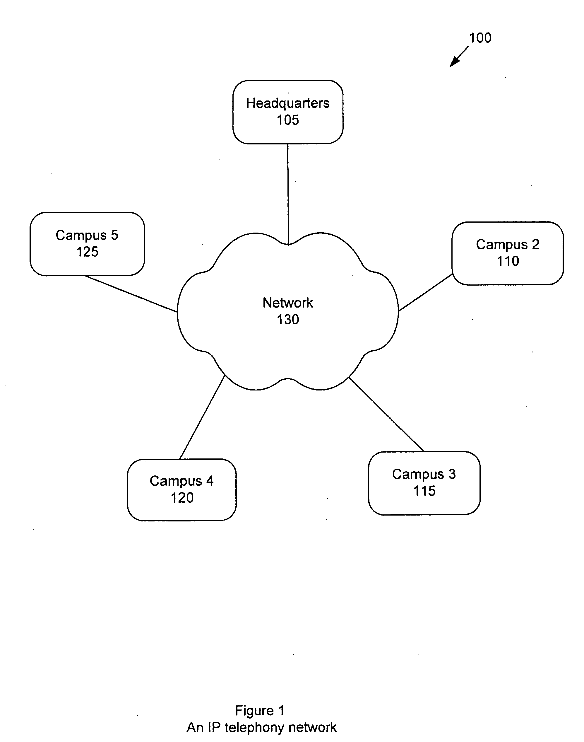
[0058]FIG. 1 is a block diagram illustrating a sample IP telephony network 100 that has five sites, 105, 110, 115, 120 and 125, called “Headquarters,”“Campus 2,”“Campus 3,”“Campus 4” and “Campus 5” respectively. Each site 105, 110, 115, 120 and 125 is connected to a network 130 which may be the Internet, WAN, LAN or other network known in the art.

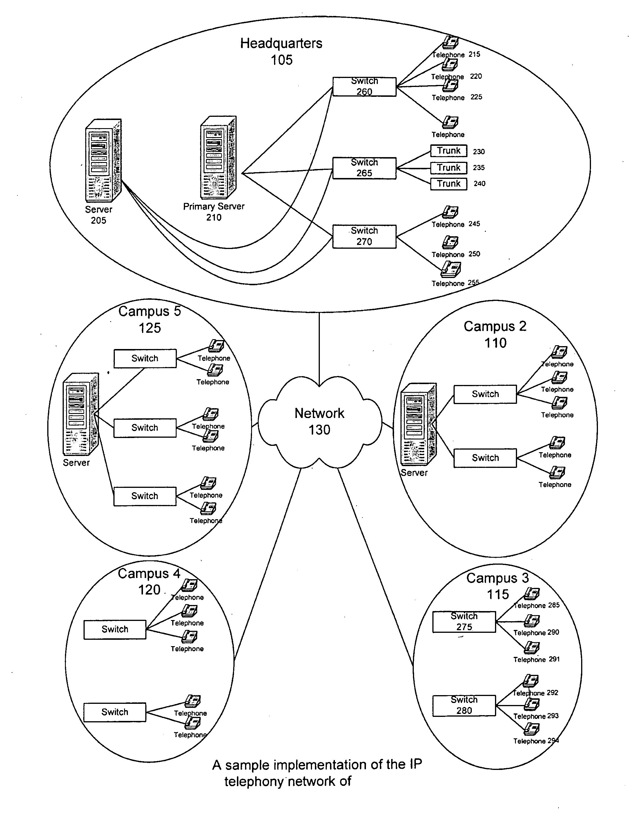
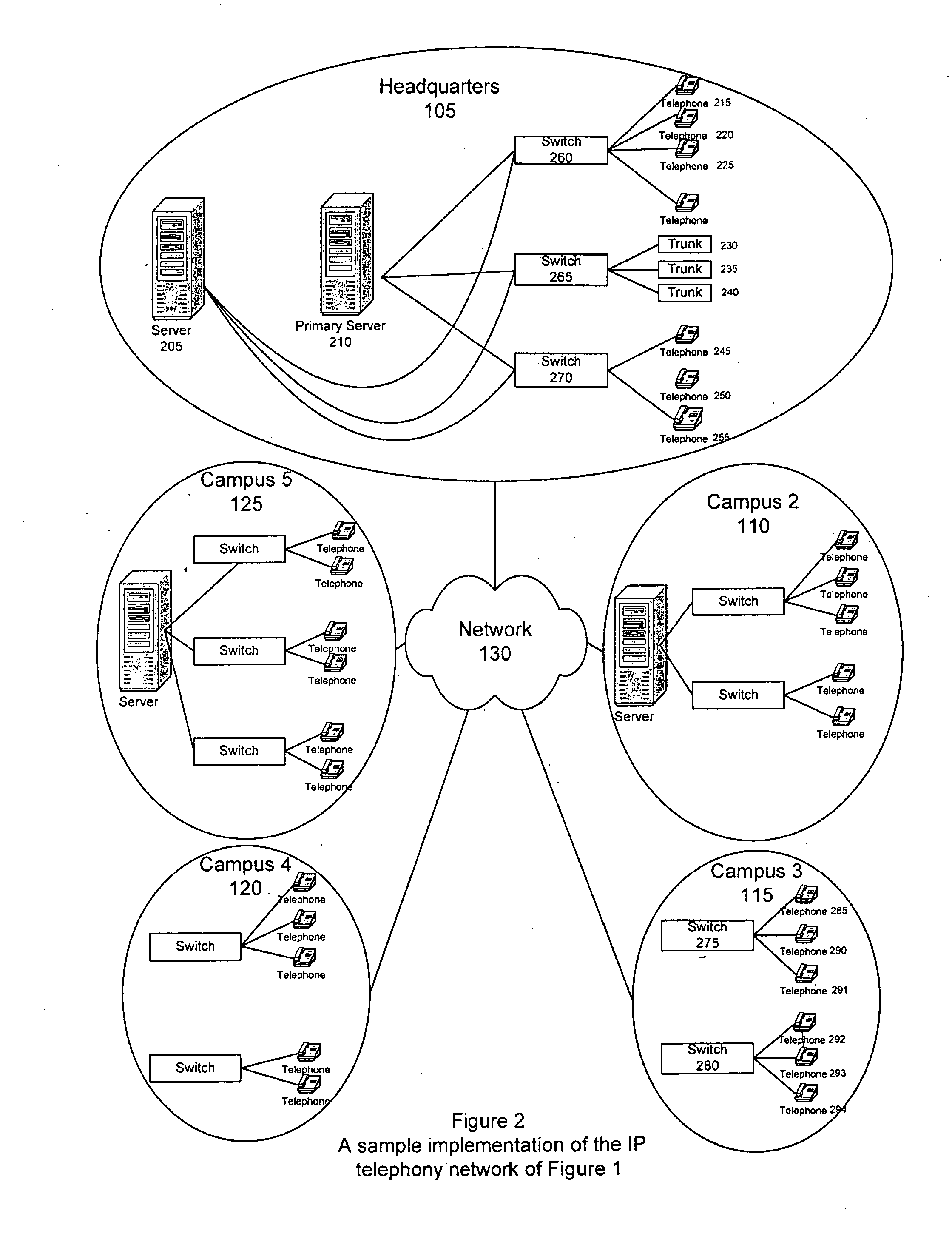
[0059]FIG. 2 is a sample implementation of the IP telephony network of FIG. 1, shown in more detail. The headquarter site 105, for example, is composed of a server 205, a primary server 210, three switches 260, 265 and 270, seven telephone extensions 215, 220, 225, 245, 250 and 255 and three trunks 230, 235 and 240. Campus 3115, on the other hand, is composed of no servers, two switches 275 and 280 and six telephone extensions 285, 290, 291, 292, 293 and 294. Each extension or trunk is connected to a switch, and each site is coupled to the network. Each extension, trunk, switch and server is located at a site in the network. A site may or m...


PUM


Abstract

A system and method for managing an IP telephony network that uses a configuration map for organizing sites in a tree-like hierarchy. The system is capable of managing the addition, removal and movement of IP telephony elements within an IP telephony network and locating services and IP telephony elements within the IP telephony network in an efficient manner.

Description

CROSS REFERENCE TO RELATED APPLICATIONS[0001]This application is a continuation of U.S. patent application Ser. No. 10 / 424,491, titled “IP Telephony Network Using A Configuration Map For Organizing Sites In A Tree-Like Hierarchy,” filed Apr. 25, 2003 which is incorporated by reference herein in its entirety.BACKGROUND OF THE INVENTION[0002]1. Field of the Invention[0003]The present invention relates to an IP telephony network using a configuration map for organizing sites in a tree-like hierarchy. The present invention specifically relates to the management of the addition to, removal from and movement of IP telephony elements within an IP telephony network. The present invention further relates to the locating of services and IP telephony elements within the IP telephony network.[0004]2. Description of Background Art[0005]An IP telephony network may generally be composed of a number sites or “campuses.” Each site may have any number of interconnected servers, switches, extensions a...

Claims


Application Information

Patent Timeline
Patent Type & Authority Applications(United States)
IPC IPC(8): H04L12/28H04L12/66
CPCH04L12/66H04L45/48H04L41/085H04L41/0893H04M3/2263H04M7/0081H04L1/22H04L45/60
Inventor MILLER, THOMAS E.TONOGAI, DALE C.NADIMPALLI, KISHOREWINTER, STEPHEN M.
Owner MITEL NETWORKS INC
Why Eureka
Try Eureka