Thermal control covers

a technology of thermal control and cover, applied in the direction of indirect heat exchangers, lighting and heating apparatuses, laminated elements, etc., can solve the problems of exceeding reducing the temperature of gas below engineering design temperature limits, and causing undesirable thermal stresses, so as to reduce thermal stresses and touch labor, reduce the effect of temperature change of an object, and minimize bottlenecks in production lines

Active Publication Date: 2007-03-27
THE BOEING CO
View PDF12 Cites 0 Cited by
  • Summary
  • Abstract
  • Description
  • Claims
  • Application Information

AI Technical Summary

Benefits of technology

[0008]Embodiments of the present invention provide an apparatus and method for mitigating temperature changes of an object. Advantageously, embodiments of the present invention can enable pressure testing to be performed without temperature excursions beyond engineering design temperature limits and without insertion of excessive delays. This can result in reductions in thermal stresses and touch labor, and can help minimize bottlenecks in production lines. Also, according to another embodiment of the present invention, an apparatus for mitigating temperature changes of an object can be fabricated quickly and inexpensively using rapid prototyping manufacturing techniques.
[0009]According to an embodiment of the present invention, a heat transfer cover is provided for mitigating temperature changes of an object. The cover includes a cover body configured to receive therein the object. A plurality of heat transfer channels are defined in an interior of the cover body, and the channels are arranged to transport a heat transfer fluid in thermal communication with the object. An inlet port is configured to connect the plurality of channels with a source of the heat transfer fluid.
[0011]According to another aspect of the present invention, at least a first end of the cover body may define an opening, and the at least first end of the cover body and the object are substantially sealed at the opening. This permits any instrumentation that may be fitted to the object to remain uninfluenced by flow of the heat transfer fluid in the cover body.
[0012]According to another embodiment of the present invention, a method is provided for mitigating temperature changes of an object. An object is received in a cover. Temperature of the object is caused to change. A heat transfer fluid in thermal communication with an exterior of the object is flowed through an interior of the cover.
[0013]According to another embodiment of the present invention, a method is provided for fabricating a heat transfer cover for mitigating temperature changes in an object. Based on an exterior of the object, a cover for the object is defined in a computer-aided-design file, and an interior of the cover has a plurality of heat transfer channels. A three-dimensional model file is generated from the computer-aided-design file, and a rapid-prototyping procedure is performed to create the cover from the three-dimensional model file.

Problems solved by technology

As a result, during a pressurization cycle of pressure testing the N2 gas may heat up to temperatures that exceed engineering design temperature limits of the UUT.
As a result, during a depressurization cycle of pressure testing the N2 gas temperature may drop below engineering design temperature limits for the UUT.
Such temperature excursions can induce undesirable thermal stresses.
For a pressure vessel, exceeding engineering design temperature limits may causes severe consequences.
In such a case, operational lifetime of the pressure vessel may be shortened (that is, a number of allowed pressurization cycles may be limited).
However, this currently known method results in lengthy cycle times for the pressure testing process.
For example, each pressurization / depressurization cycle of a pressure test may take over an hour.
However, there is an unmet need in the art for a system and method for mitigating temperature changes during pressure testing without inserting excessive delays into the pressure testing process.

Method used


Image

  • Thermal control covers
  • Thermal control covers
  • Thermal control covers

Examples


Embodiment Construction

[0019]By way of overview, embodiments of the present invention provide an apparatus and method for mitigating temperature changes of an object. Advantageously, embodiments of the present invention can enable pressure testing to be performed without temperature excursions beyond engineering design temperature limits and without insertion of excessive delays. This can result in reductions in touch labor and can help minimize bottlenecks in production lines. Also, according to another embodiment of the present invention, an apparatus for mitigating temperature changes of an object can be fabricated quickly and inexpensively using rapid prototyping manufacturing techniques.

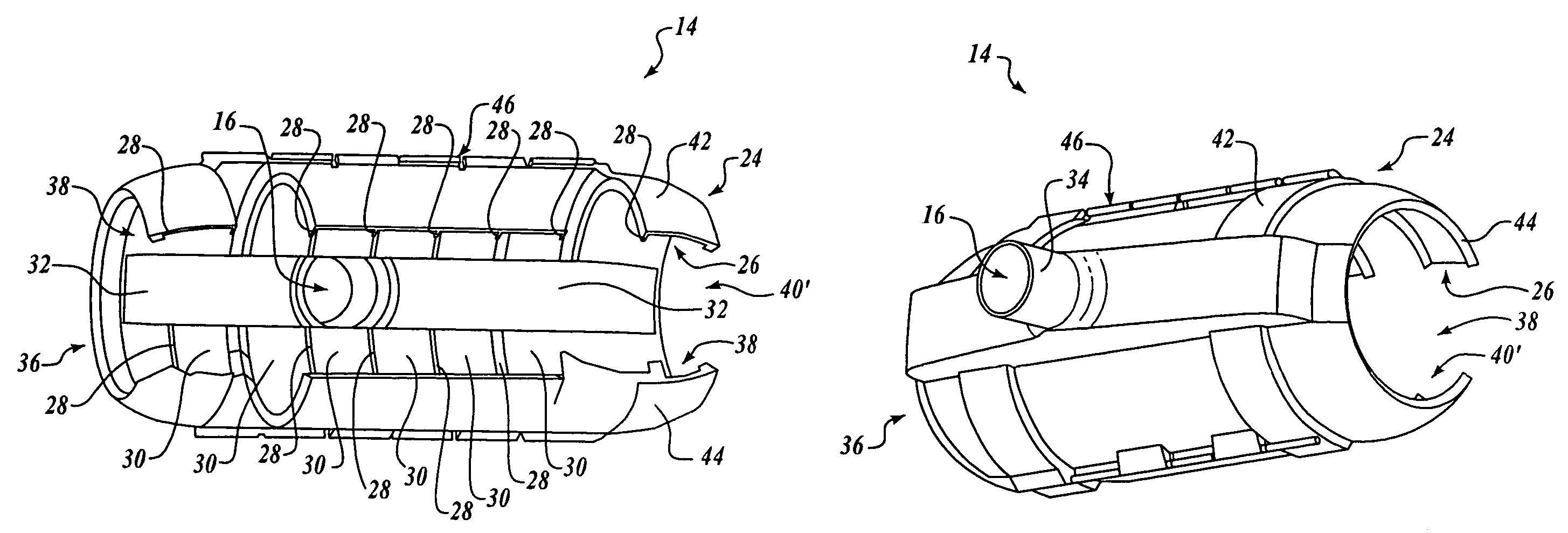
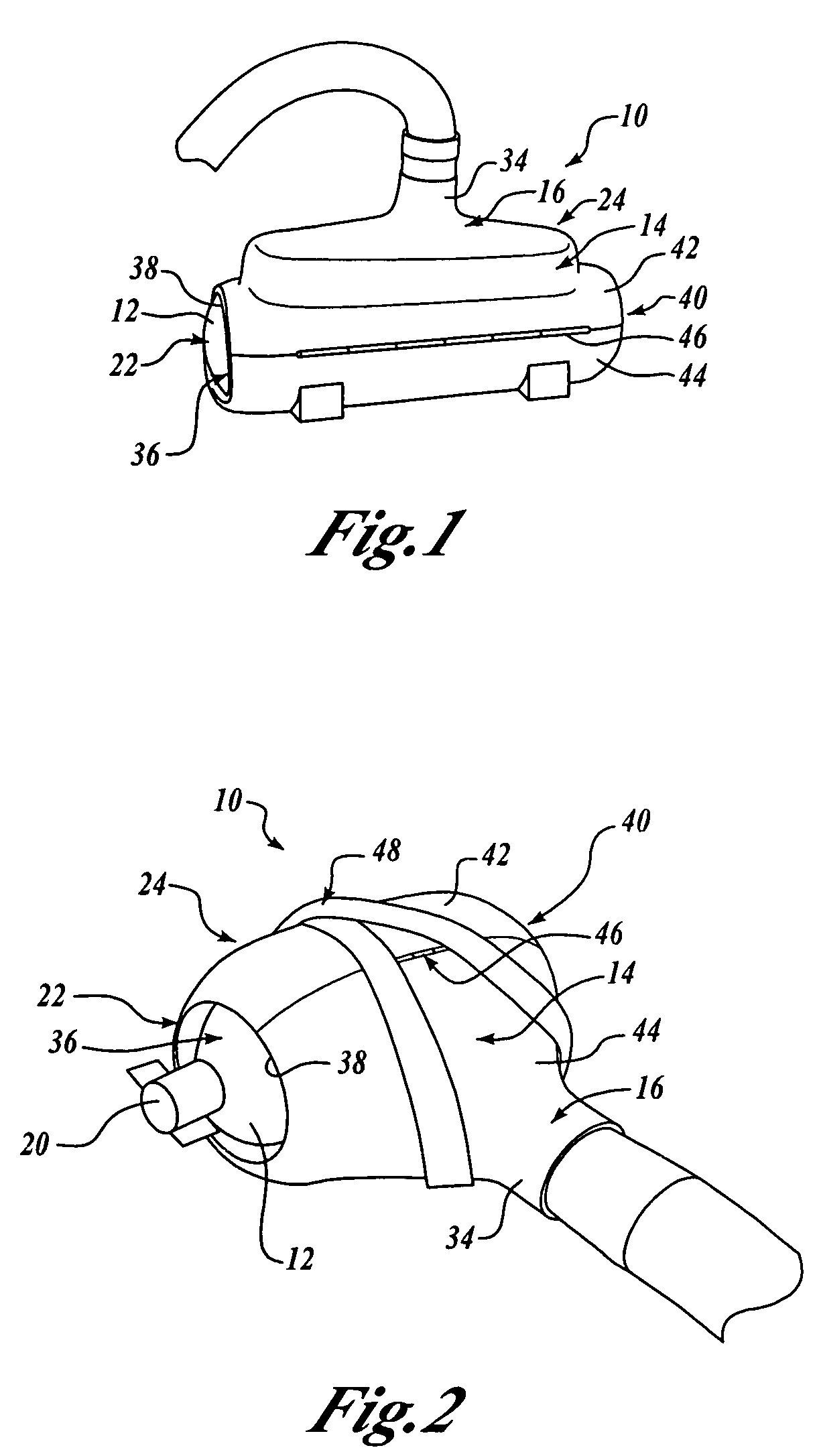
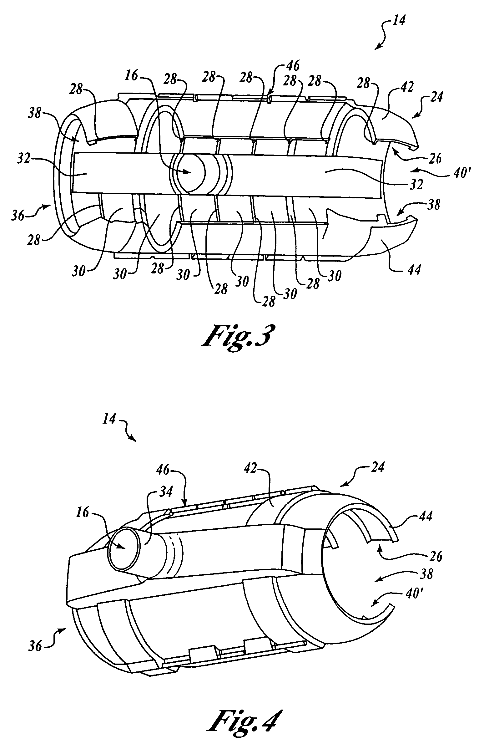
[0020]Referring now to FIGS. 1 and 2, a cover 10 is provided for mitigating temperature changes of an object 12. The cover 10 includes a cover body 14 configured to receive therein the object 12. A plurality of heat transfer channels (not shown in FIG. 1) are defined in an interior of the cover body 14, and the channe...


PUM


Abstract

A heat transfer cover mitigates temperature changes of an object. A cover body is configured to receive the object. A plurality of heat transfer channels are defined in an interior of the cover body. The channels are arranged to transport a heat transfer fluid in thermal communication with the object. An inlet port is configured to connect the plurality of channels with a source of the heat transfer fluid. An interior surface of the cover body may substantially conform to a shape of an exterior of the object. A plurality of lands may be defined in the interior of the cover body. The lands are arranged to engage the exterior of the object. The heat transfer channels may be defined between adjacent lands. At least a first end of the cover body may define an opening. The at least first end and the object are substantially sealed at the opening.

Description

FIELD OF THE INVENTION[0001]This invention relates generally to environmental testing and, more specifically, to pressure testing.BACKGROUND OF THE INVENTION[0002]Acceptance testing of production items often includes environmental testing, such as pressure testing. For example, a pressure vessel or other production item may be pressurized to verify integrity.[0003]Typical current pressure test processes utilize dry nitrogen (N2) gas to pressurize a unit under test. N2 gas is used instead of water in order to maintain internal cleanliness of the unit under test (UUT).[0004]As is known, in a closed gaseous system when pressure increases, temperature also increases. As a result, during a pressurization cycle of pressure testing the N2 gas may heat up to temperatures that exceed engineering design temperature limits of the UUT. As is also known, in a closed gaseous system conversely when pressure decreases, temperature also decreases. As a result, during a depressurization cycle of pres...

Claims


Application Information

Patent Timeline
Patent Type & Authority Patents(United States)
IPC IPC(8): F28F7/02F24H3/00F28F3/12
CPCF28F3/12F28D2021/0077B33Y80/00
Inventor NEALON, JOSEPH M.SCHULTZ, STEPHEN J.
Owner THE BOEING CO
Why Eureka
Try Eureka