Laser Apparatuses With Large-Number Multi-Reflection Pump Systems

Active Publication Date: 2009-02-05
OPTTON
View PDF10 Cites 14 Cited by
  • Summary
  • Abstract
  • Description
  • Claims
  • Application Information

AI Technical Summary

Problems solved by technology

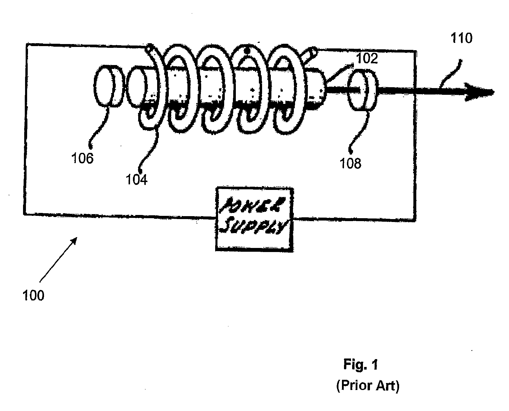
However, since the laser beam travels through the crystal rod many times, the quality of light beam, e.g., the regularity of its wavefront, will be degraded by the inhomogeneity of the rod including the uneven thermal distribution in the rod.
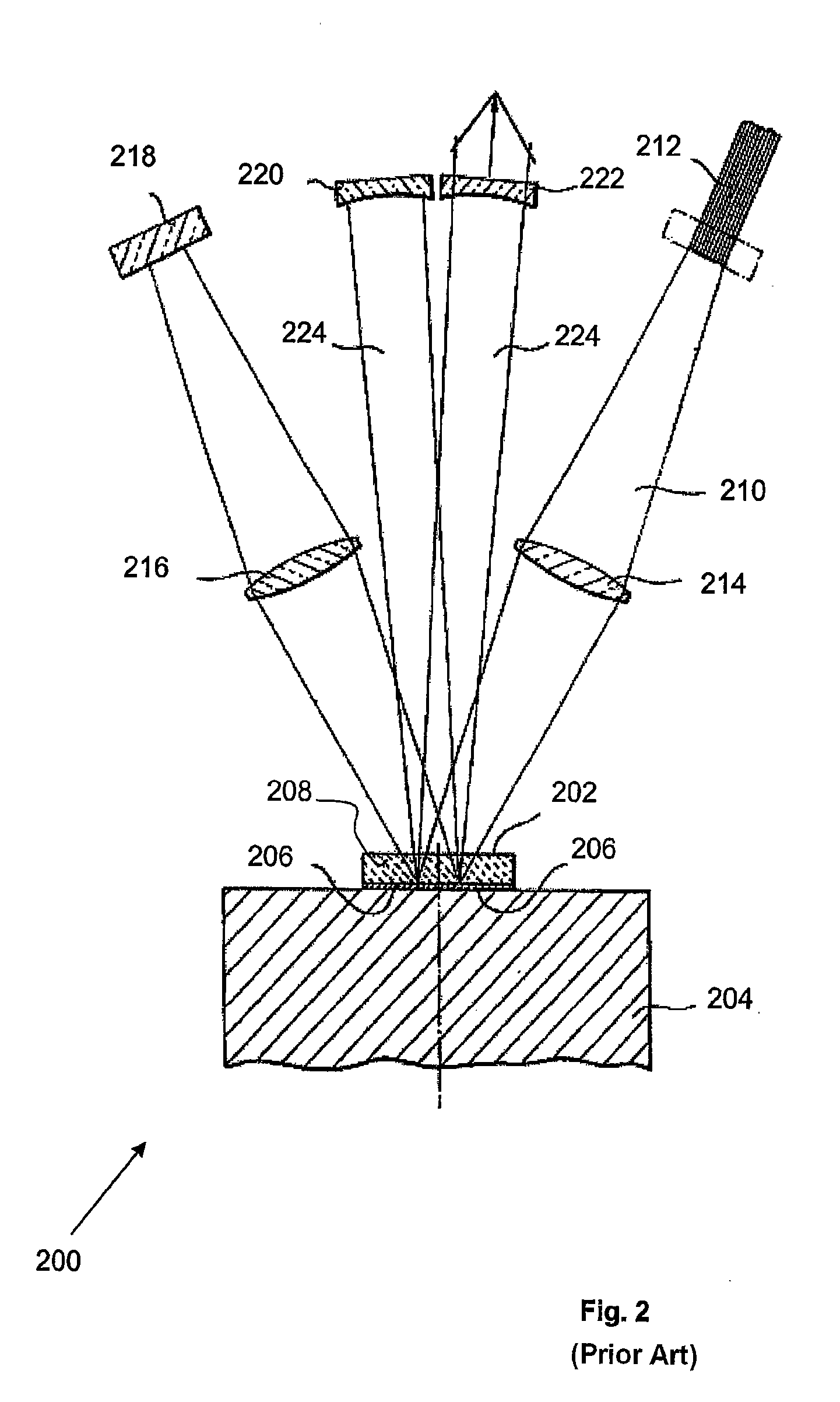
Although more passes of pump light through the disk are required to produce a higher power laser beam, all disclosed methods can only provide limited numbers of passes of pump light through the disk.
The disadvantages of this method are: (1) the number of passes of the pump light through the active mirror is limited by the number of the individual spherical mirrors (e.g., 4 individual spherical mirrors provide 8 passes), (2) the number of the individual spherical mirrors is limited by the size of the mirror, and (3) the mechanical system for supporting a plurality of individual spherical mirrors is complex and costly.
Similarly, the disadvan

Method used


Image

  • Laser Apparatuses With Large-Number Multi-Reflection Pump Systems
  • Laser Apparatuses With Large-Number Multi-Reflection Pump Systems
  • Laser Apparatuses With Large-Number Multi-Reflection Pump Systems

Examples


Embodiment Construction

Multi-Reflection System Using Three Spherical Mirrors

[0049]FIG. 5 shows one embodiment of pump system in which a large number of passes of the pump light through the active mirror can be realized. The pump system 500 comprises a large concave spherical mirror 502 and two small concave spherical mirrors 504 and 506. In an implementation, one of the small mirrors can be a simple mirror (not an active mirror) and the other one of the small mirrors can be an active mirror. In another implementation, both small mirrors can be active mirrors.

[0050]For example, all mirrors have the same radii R. The center of curvature of the large spherical mirror 502 is located at point O, which is the central point between small spherical mirrors 504 and 506. The centers of curvature of spherical mirrors 504 and 506 are located at points A and B, respectively, on the large spherical mirror 502. The arc between A and B is d degree. All points A, B and O are in a meridional plane. In other words, the plan...


PUM


Abstract

A large number of passes of pump light through an active mirror in a solid state disk laser is realized using a pair of coupled imaging systems, where the optical axes of imaging systems are not coincident. Two imaging systems are optically coupled, so that an image of the first imaging system is an object of the second imaging system, and vice versa. An active mirror is disposed at the object or image plane, or at the focal plane of any one of the coupled imaging systems, where the position of the reflected pump beam during the multi-reflection between the first and second imaging systems is substantially unchanged.

Description

CROSS-REFERENCES TO RELATED APPLICATIONS[0001]This application is a continuation in part of application Ser. No. 11 / 376,792 filed Mar. 15, 2006, which is a continuation of provisional application No. 60 / 662,922 filed Mar. 16, 2005, now abandoned, the disclosures of which are incorporated herein by reference.FIELD OF THE INVENTION[0002]The present invention relates to a pump system for a solid state laser, or more specifically, to a pump system that provides a large number of passes of the pump light through an active mirror with simple optical means.BACKGROUND OF THE INVENTION[0003]Currently, various lasers have been available for various applications, ranging from low power semiconductor lasers for opto-electronic devices to high power solid state lasers for manufacturing, which is kin to the first laser invented by Maiman in 1967 (U.S. Pat. No. 3,353,115). In contrast to other light sources that emit incoherent light, a laser emits a coherent light beam. Theoretically, a coherent ...

Claims


Application Information

Patent Timeline
IPC IPC(8): H01S3/091
CPCH01S3/0405H01S3/042H01S3/0604H01S3/061H01S3/09415H01S3/07H01S3/08068H01S3/094084H01S3/0621
Inventor WANG, ZHIJIANGWANG, YING
Owner OPTTON
Why Eureka
Try Eureka