
Wind Generator

a generator and wind power technology, applied in the direction of propellers, propulsive elements, water-acting propulsive elements, etc., can solve the problem of not being able to achieve the rotation of the blades, and achieve the effect of reducing the braking of the rotation

Inactive Publication Date: 2009-02-05
MARTINEZ PENADES BERNARDO
View PDF3 Cites 4 Cited by
  • Summary
  • Abstract
  • Description
  • Claims
  • Application Information

AI Technical Summary

Benefits of technology

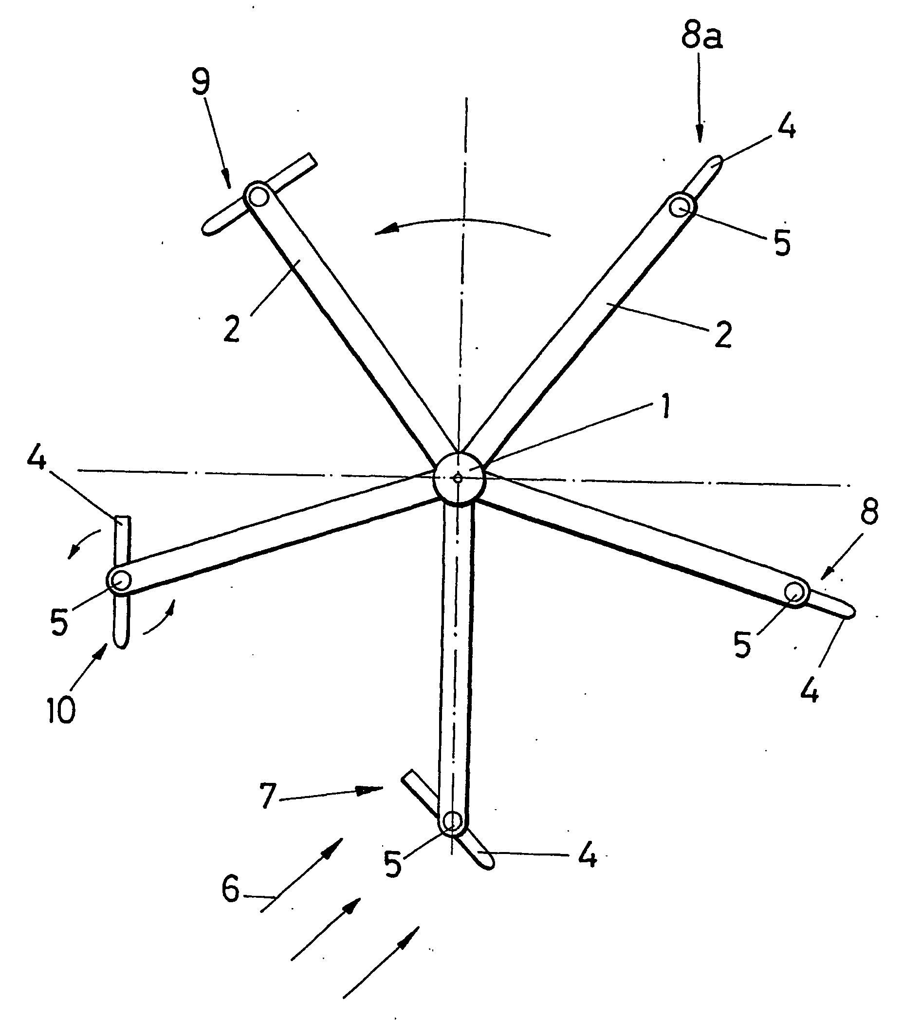
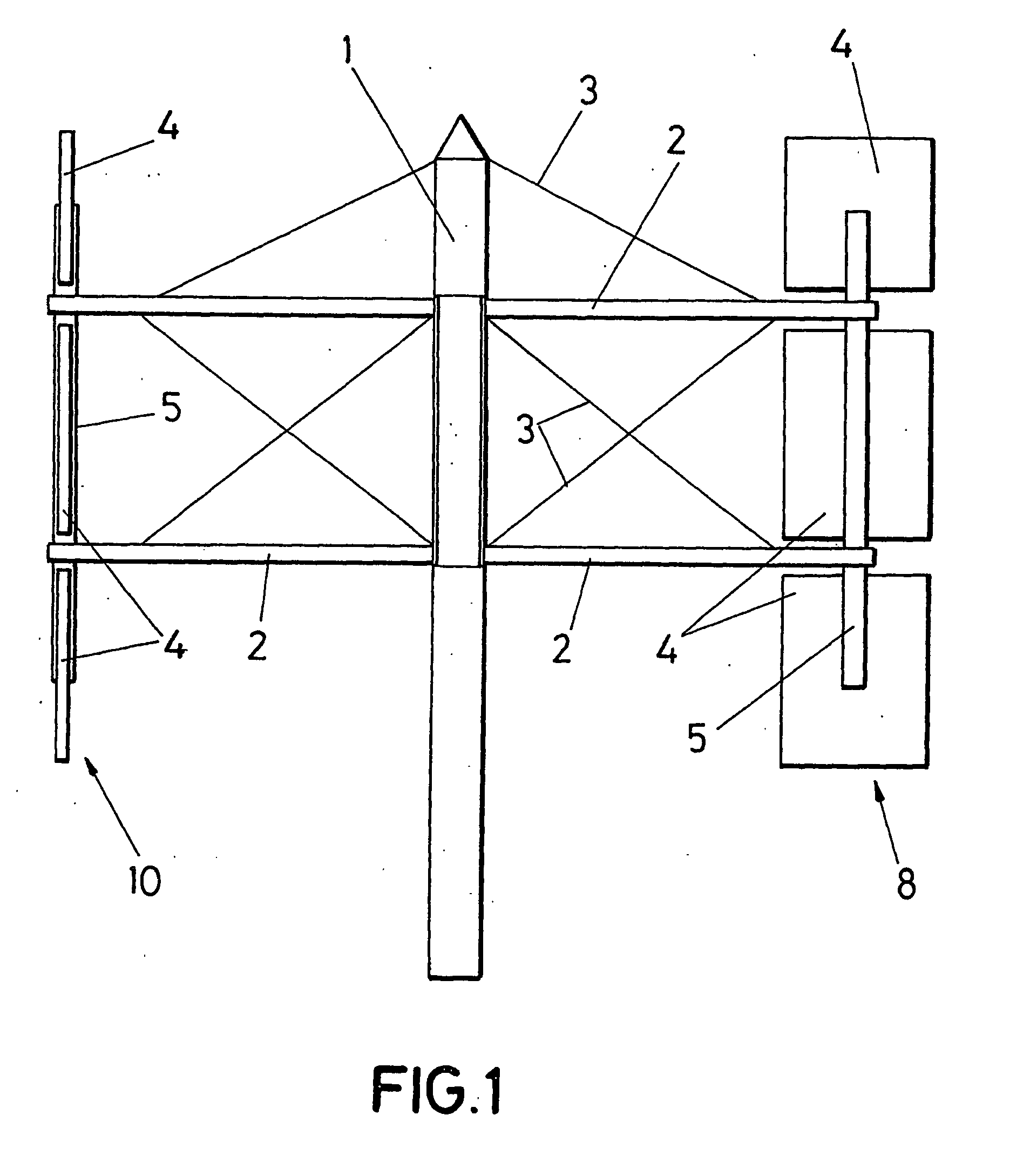
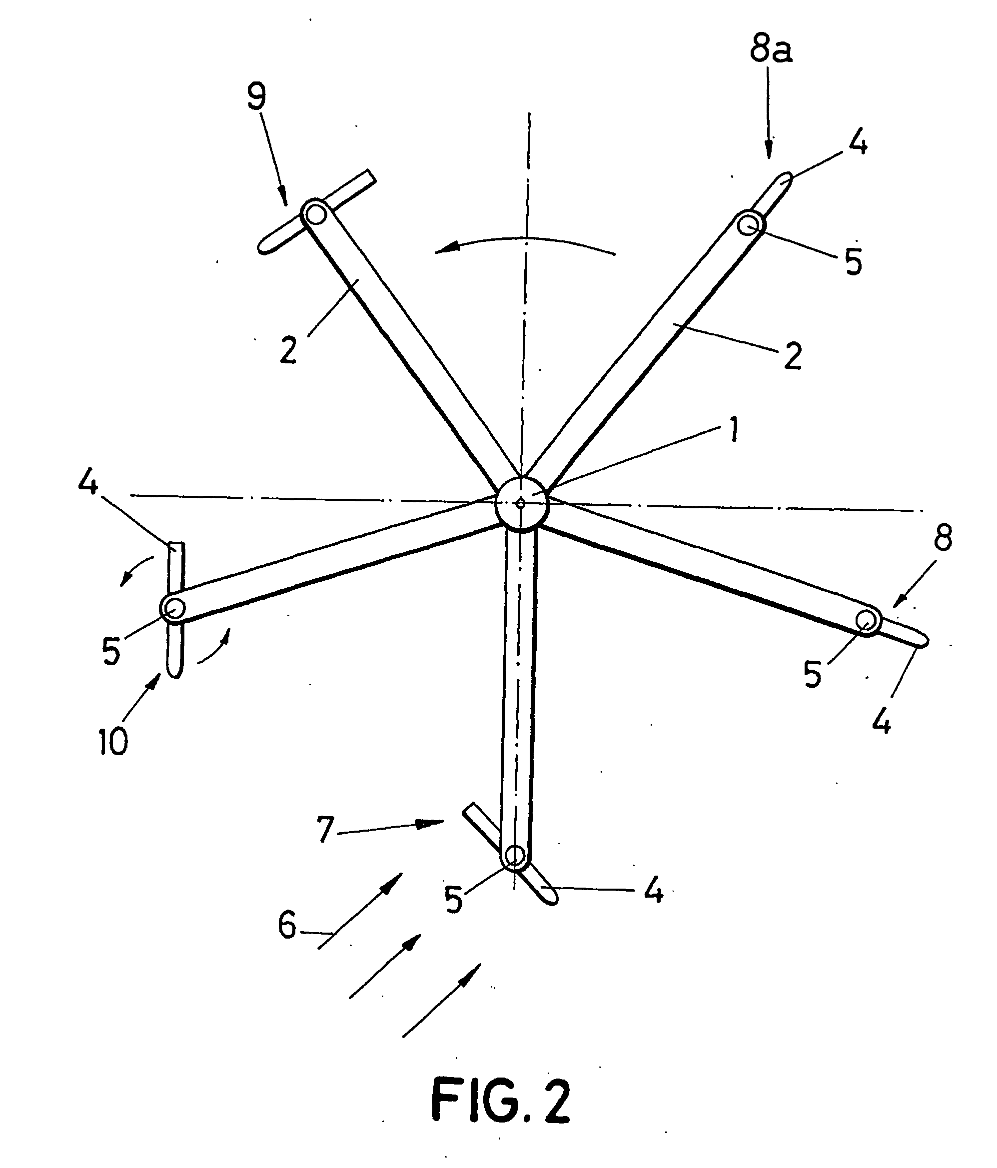
[0001]The present invention relates to a wind generator that includes vertical blades which rotate around the tower and which also rotate about themselves with the aim of having them facing the wind during the angular displacement that favours the rotation of the blades around the tower, and to locate them parallel to the wind during the rest of the angular displacement, in such a way that reduces the braking of the rotation which the blades produce during the angular displacement when they are not facing the wind.
[0006]In order to solve the drawbacks stated above, the invention has developed a novel wind generator which, as with those of the state of the art, provides for the use of a tower and a set of blades; and is characterised in that the blades are vertical for which it comprises means of attachment of the vertical blades to the tower and means of rotation of said vertical blades about themselves, in such a way that, unlike in the state of the art, the blades rotate around the tower and furthermore, as they rotate about themselves, this permits them to face the direction of the wind during the angular displacement that favours the rotation of the blades around the tower, and at the same time it permits the vertical blades to be located parallel to the direction of the wind during the rest of the angular displacement, such that the braking of the rotation that is produced is reduced.
[0007]Moreover, the invention provides for the incorporation of means of suppression of the vertical blades when they pass from the parallel position to the position facing the direction of the wind, in such a way that this novel characteristic minimises the braking which each vertical blade produces during that change of position.
[0008]The configuration described permits the efficiency of the wind generator to be improved considerably, and it also allows its application both when the wind is weak and in regions where winds are strong, by permitting the rotation of the blades about themselves to be regulated and their surface to be varied, which allows them to be coupled to the needs of each moment.
[0017]Consequently, the configuration described permits the maximum efficiency of the inventive wind generator to be obtained at any moment, by permitting the blades to rotate about themselves and by permitting the surface of them to vary when they pass from the parallel position to the position facing the wind direction.

Problems solved by technology

This type of generator presents the drawback that when the wind is 25 strong the rotation of the blades has to be halted in order to prevent them from breaking, and on the other hand, when the wind is weak no rotation of the blades is achieved.

Method used


Image

  • Wind Generator
  • Wind Generator
  • Wind Generator

Examples


Embodiment Construction

[0006]In order to solve the drawbacks stated above, the invention has developed a novel wind generator which, as with those of the state of the art, provides for the use of a tower and a set of blades; and is characterised in that the blades are vertical for which it comprises means of attachment of the vertical blades to the tower and means of rotation of said vertical blades about themselves, in such a way that, unlike in the state of the art, the blades rotate around the tower and furthermore, as they rotate about themselves, this permits them to face the direction of the wind during the angular displacement that favours the rotation of the blades around the tower, and at the same time it permits the vertical blades to be located parallel to the direction of the wind during the rest of the angular displacement, such that the braking of the rotation that is produced is reduced.

[0007]Moreover, the invention provides for the incorporation of means of suppression of the vertical blad...


PUM


Abstract

Comprising a tower (1) and a set of vertical blades (4) which rotate around the tower (1) and which in turn rotate about themselves on a shaft (5) in order to face the direction of the wind (6) during the angular displacement that favours the rotation of the blades (4) around the tower (1) and in order to locate them parallel to the direction of the wind (6) during the rest of the angular displacement, reducing the braking of the blades when passing from their position parallel to the wind direction to the position facing it. The blades (4) comprise means (11-13) of suppression of the surface of the blade when it passes from the parallel position to the position facing the direction of the wind (6), minimising the braking which the blade produces during the change of said position. It permits maximum efficiency to be obtained with both weak and strong winds.

Description

OBJECT OF THE INVENTION[0001]The present invention relates to a wind generator that includes vertical blades which rotate around the tower and which also rotate about themselves with the aim of having them facing the wind during the angular displacement that favours the rotation of the blades around the tower, and to locate them parallel to the wind during the rest of the angular displacement, in such a way that reduces the braking of the rotation which the blades produce during the angular displacement when they are not facing the wind.[0002]Another object of the invention is to provide means of suppression of the surface of the blades when they pass through the position parallel to the wind to the position facing the same, in such a way that during that change of direction the braking which the blades produce during that transition is also minimised, such that maximum efficiency is obtained from the wind generator.PRIOR ART OF THE INVENTION[0003]The use of wind generators or aero-...

Claims


Application Information

Patent Timeline
Patent Type & Authority Applications(United States)
IPC IPC(8): F03D3/00
CPCF03D3/005F03D3/067F03D3/068Y02E10/74F05B2240/214F05B2240/313F03D7/0232
Inventor MARTINEZ PENADES, BERNARDO
Owner MARTINEZ PENADES BERNARDO
Learn More