
Hub-profile connection system for axial fan and axial fan provided with this connection system

a technology of axial fan and connection system, which is applied in the direction of propellers, propulsive elements, water-acting propulsive elements, etc., can solve the problems of low static and dynamic loads, consequent cost saving and vibration abatement, and achieve cost saving, vibration abatement, and static and dynamic load reduction

Inactive Publication Date: 2009-02-05
R E M HLDG
View PDF6 Cites 4 Cited by
  • Summary
  • Abstract
  • Description
  • Claims
  • Application Information

AI Technical Summary

Benefits of technology

[0004]It is the main object of the present invention to provide a hub-profile connection system for axial fans, which, in relation to the known hinged or flexible rigid constraint connection systems, presents low static and dynamic loads, a better construction simplicity and a-higher resistive moment.
[0006]In relation to the known art, the hub-profile connection system of the present invention offers the following advantages:
[0007]compared with rigid constraint systems, lower static and dynamic loads, with consequent cost saving and vibration abatement;
[0008]with respect to hinged constraint systems, a particular construction simplicity, the possibility of graduating the freedom of movement on the vertical, plane as desired and the absence of wear;
[0009]unlike flexible constraint connection systems, a higher resistive moment (and thus the possibility of using more cost-effective materials with lower mechanical features, the section being equal), a higher torsional strength and a higher rigidity on the vertical plane (with consequent solution of the problem of excessive profile lowering in large diameter fans).

Problems solved by technology

compared with rigid constraint systems, lower static and dynamic loads, with consequent cost saving and vibration abatement;

Method used


Image

  • Hub-profile connection system for axial fan and axial fan provided with this connection system
  • Hub-profile connection system for axial fan and axial fan provided with this connection system
  • Hub-profile connection system for axial fan and axial fan provided with this connection system

Examples


Embodiment Construction

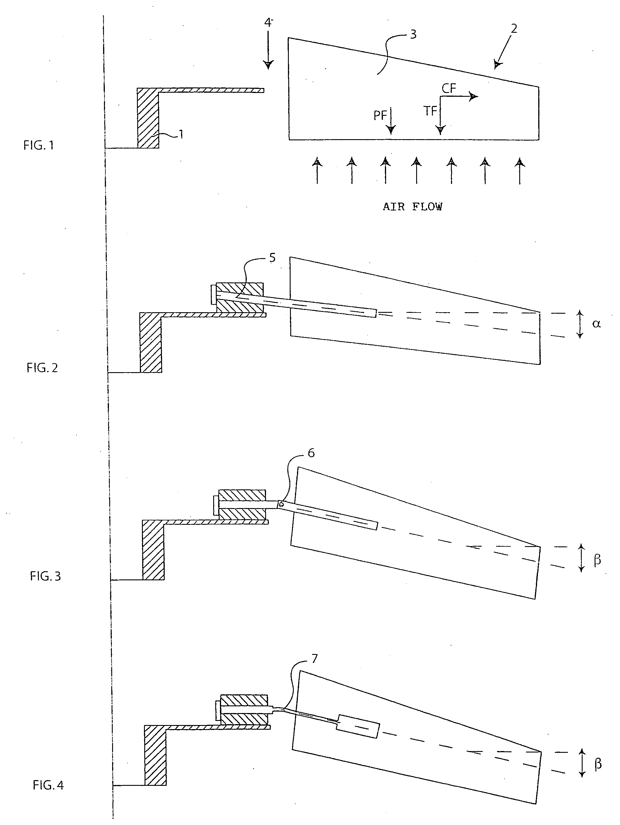
[0016]For a better understanding of the system according to the present invention, FIG. 1 shows the most important forces acting on a running axial fan blade, i.e. centrifuge force CF, having radial direction, the traction aerodynamic force TF, with axial direction, and weight force PF, with axial direction.

[0017]These forces generate a bending moment and a torque, with static and dynamic loads which are particularly relevant for the structural dimensioning calculations of the fan. A reduction of these moments allows important savings.

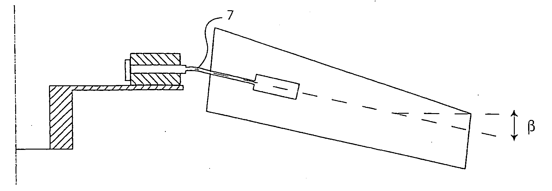
[0018]Connection 4 between hub 1 and profile 3 of blade 2 of an axial fan is currently mainly made in three ways: with a rigid system, with a hinged system and with a flexible system.

[0019]The three cases will be briefly described, indicating the main advantages and the disadvantages thereof, in order to compare them with the invention and highlight its superiority.

[0020]In the case of a rigid system connection (FIG. 2), the hub-profile connection is m...


PUM


Abstract

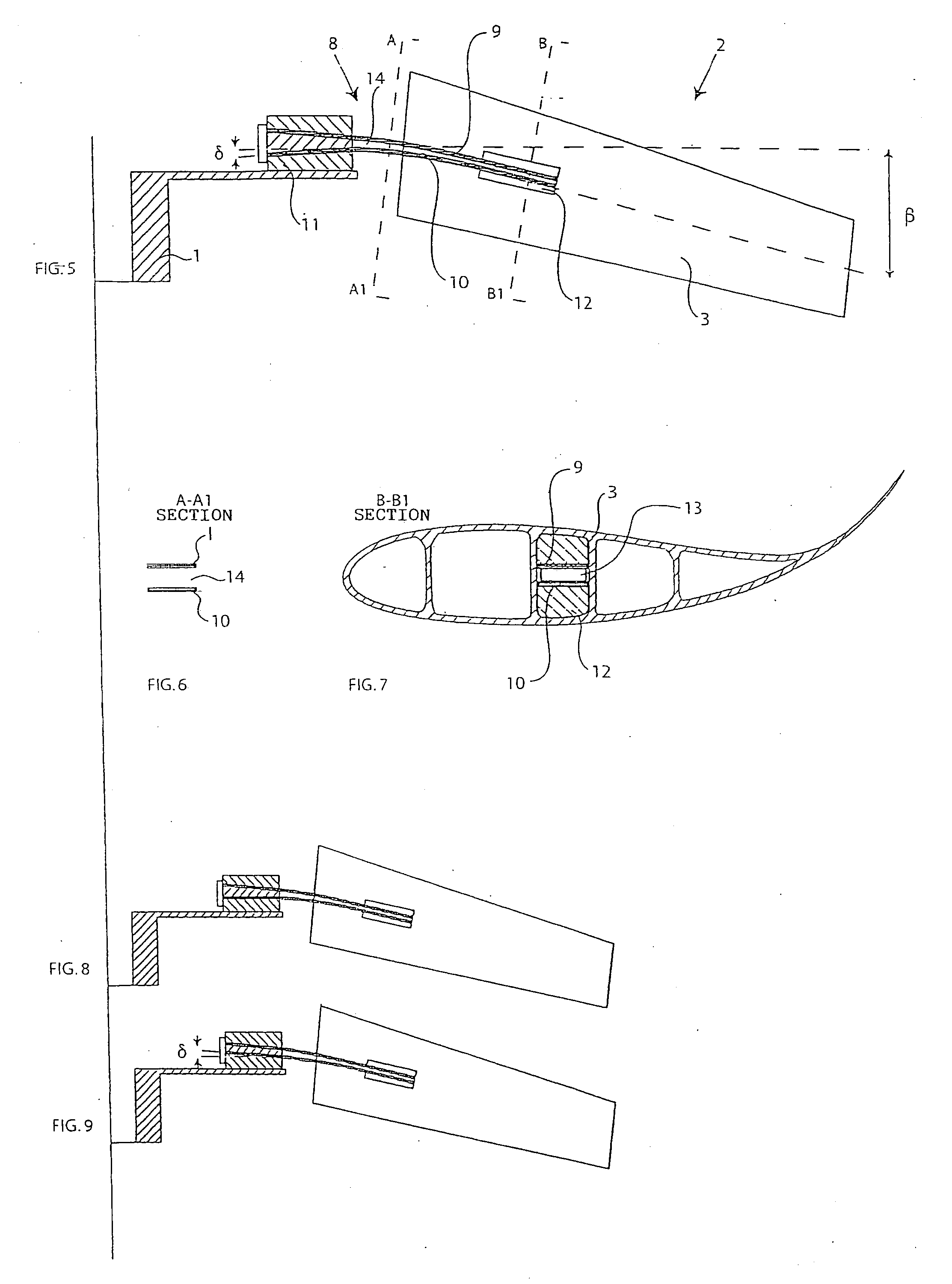
A hub-profile connection system for axial fan, consisting of a hub to which one or more blades provided with an air displacement profile are fixed, said system comprising two separate and distinct flexible elements both fixed on-hub side, to a fastening block and, on blade side, to a corresponding fastening block.Compared with the rigid constraint systems, the system of the invention offers lower static and dynamic loads, with consequent cost saving and vibration abatement. With respect to hinged constraint systems, there are the advantages of a particular construction simplicity, the possibility of graduating the freedom of movement on the vertical plane as desired and the absence of wear. Unlike flexible constraint connection systems, the invention displays a higher resistive moment (and thus the possibility of using more cost-effective materials with lower mechanical features, the section being equal), a higher torsional strength and a higher rigidity on the vertical plane (with consequent solution of the problem of excessive profile lowering in large diameter fans).

Description

FIELD OF THE INVENTION[0001]The present invention relates to a hub-profile connection system for axial fan. The same invention further extends to the axial fan provided with this connection system.PRIOR ART[0002]Axial fans are commonly used where large amounts of air need to be moved, overcoming even high static pressures, specifically in the systems in which the air is used for cooling by means of heat exchange. In this case, fans are used which may reach-very large diameters, even twenty metres.[0003]In the design of this type of fan, the connection between hub and part of the blade intended to displace the air, hereinafter called profile, is a particularly important issue, because the stresses here reach their maximum and such connection is thus a zone subject to breakage risks.SUMMARY OF THE INVENTION[0004]It is the main object of the present invention to provide a hub-profile connection system for axial fans, which, in relation to the known hinged or flexible rigid constraint c...

Claims


Application Information

Patent Timeline
IPC IPC(8): F01D5/02F01D5/30
CPCF04D29/382F04D29/34
Inventor MOSIEWICZ, ROBERTO EDUARDO
Owner R E M HLDG
Learn More