Disposable prophylaxis angle

a prophylaxis angle and dispensing technology, applied in the field of dispensing prophylaxis angles, can solve the problems of insufficient sterilization of the metal angle between uses, requiring extensive care, and bodily fluids entering the angl

Active Publication Date: 2009-02-05
YOUNG DENTAL MFG 1
View PDF24 Cites 21 Cited by
  • Summary
  • Abstract
  • Description
  • Claims
  • Application Information

AI Technical Summary

Benefits of technology

[0014]In still another aspect, a contra-angle is provided in which the drive shaft will not be subject to over-flexing during operation.

Problems solved by technology

While these were sturdy, they required extensive care to ensure against transferring disease and germs from one patient to another.
If the metal angle is not properly sealed, the bodily fluids can penetrate the angle.
Simply wiping down the metal angle between uses is not adequate sterilization.
If the grit is not removed, it might interfere with the gears, reducing the operating life of the metal angle or making it difficult to operate.
Thus, the care required for metal angles is quite extensive.
While disposable angles have provided economic and ergonomic benefits in the past, they have not been without problems.
The angles often make unwanted noise caused by contact between the drive gear and the shaft of the driven gear.
This leads to an unpleasant dental experience for the patient who may already be feeling anxious.
Additionally, the unwanted contact causes a rough operation of the gears as opposed to a desired smooth operation.
It also causes unnecessary wear and tear on the angle gears, and dentists may need to dispose of the angle sooner than should be necessary.
There is nothing to secure the drive gear within the body.
Thus, the angle of the '599 Patent is subject to undesirable noise and vibration caused by unwanted contact between the drive gear and the shaft of the driven gear.
Thus, the finger does not provide axial support for the drive gear.
Thus, the finger does not fully accomplish its goal of eliminating unwanted contact between the drive gear and the driven gear shaft.
One drawback with contra-angles, such as the one disclosed in the '599 Patent, is that the bending of the shaft makes the shaft susceptible to breakage.
During use, the shaft is rotated, and the bending can cause it to over-flex.
This over-flexing leads to breakage of the shaft.
Additionally, over-flexing of the shaft may cause the shaft to become disengaged from a dental handpiece to which it is attached.
Because the inside of the angle body is generally hollow, the shaft has nothing to secure it within the body.
If the shaft becomes disengaged, the dental procedure will be disrupted.

Method used


Image

  • Disposable prophylaxis angle
  • Disposable prophylaxis angle
  • Disposable prophylaxis angle

Examples


Embodiment Construction

[0023]While the present invention is susceptible of many different embodiments, there is shown in the drawings and will herein be described in detail preferred embodiments of the invention with the understanding that the present disclosure is to be considered an exemplification of the principles of the invention and is not intended to limit the broad aspect of the invention to the embodiments illustrated.

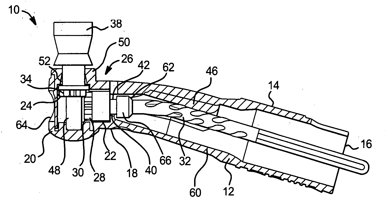
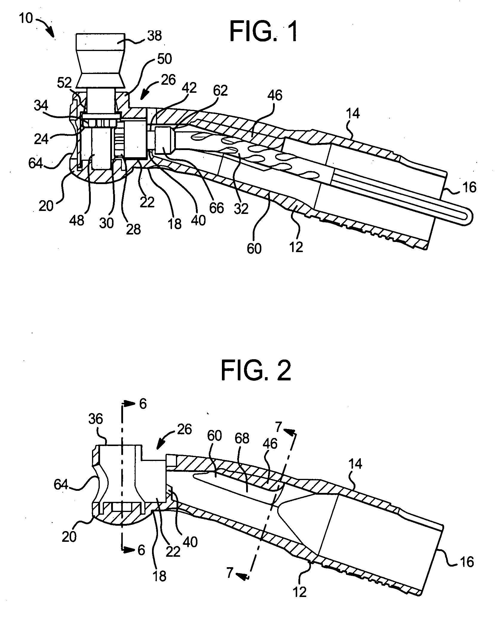
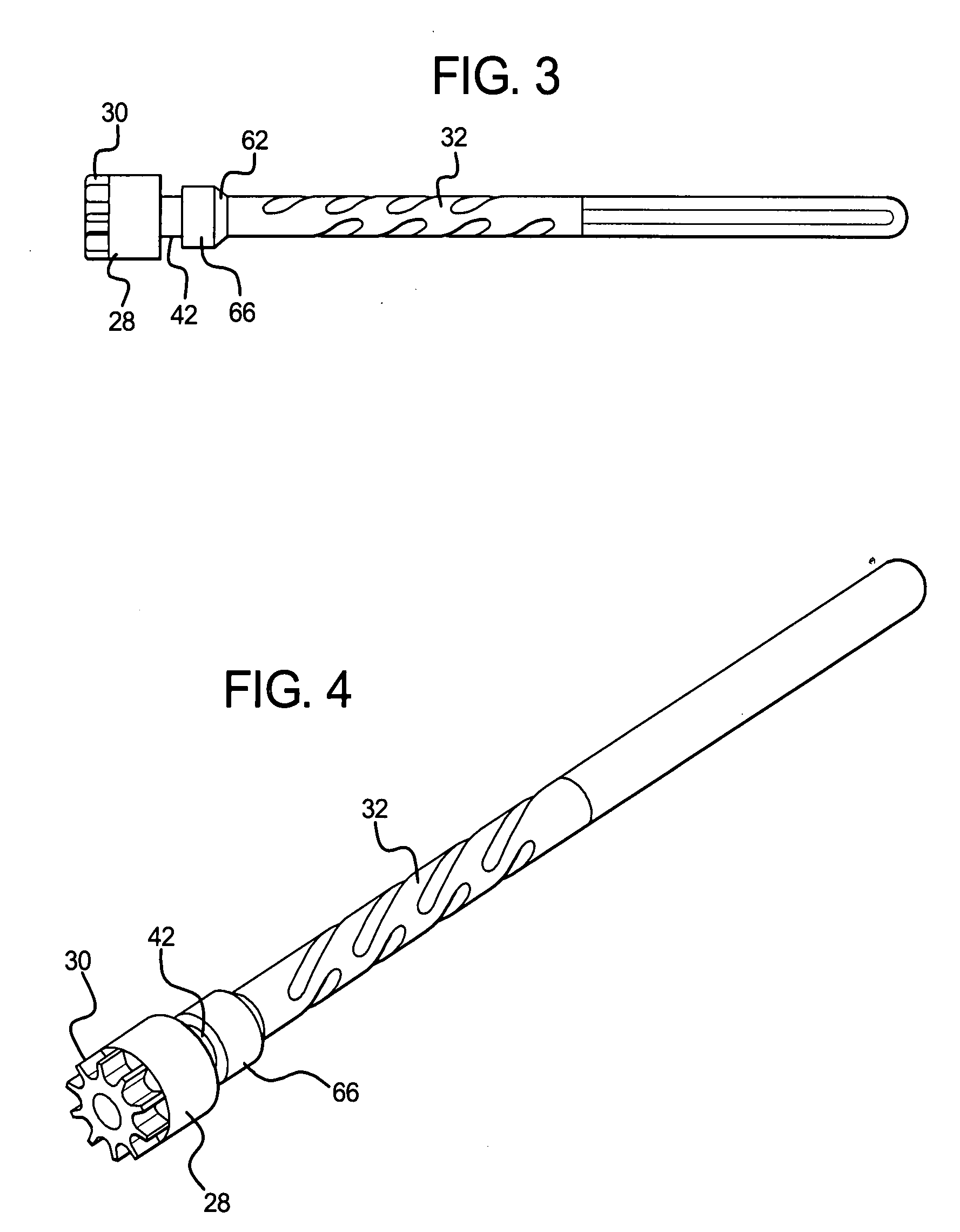
[0024]One embodiment of angle 10 of the present invention is generally shown in FIGS. 1 and 2. Angle 10 includes a body 12, a drive gear 28, a driven gear 34, and a cap 50. Body 12 includes a sleeve 14, a neck 18, and a head 20. Preferably, the sleeve 14 is formed to have a circular cross-section. The sleeve 14 has an open rear end 16, a neck 18, and a head 20. The head 20 is preferably formed as a cylinder at a right angle to the neck 18. A first axial bore 22 and a second axial bore 24 are located within the body 12. The first axial bore 22 extends through the neck 18, while the s...


PUM


Abstract

A dental prophylaxis angle includes a body, a drive gear and a driven gear. The body has a sleeve with an open rear end, a neck, a head, a first axial bore, and a second axial bore. The first axial bore is located in the neck, and the second axial bore is located in the head. The first and second axial bores communicate with each other at an intersection. A channel extends through the body from the base of the neck to the open rear end. The drive gear is adapted to be inserted into said body through said head. The drive gear includes a gear, an intermediate portion and a shaft. The shaft extends rotatably from the open rear end of the sleeve, through the first bore, and into the second bore. The intermediate portion further includes an angled leading edge. The drive gear defines a circumferential groove between said gear and said intermediate portion. The driven gear is rotatably mounted in the head and operatively connected to the drive gear. The body further includes a lip extending into the channel. The lip is adapted to be received by the groove when the drive gear is inserted through said head.

Description

TECHNICAL FIELD[0001]The present invention generally relates to dental or prophylaxis angles, and more specifically, to a disposable prophylaxis angle.BACKGROUND OF THE INVENTION[0002]Dental angles are used by dentists to clean or polish teeth. To accomplish this, dental angles carry dental bits such as prophy cups and brushes and burs. The angle allows dentists to more easily reach various surfaces of a patient's teeth when cleaning or polishing. Angles generally include a body, having a head, which has a major axis angled relative to a major axis of the body. The angle is usually ninety degrees. A drive gear and a driven gear are carried in the body in a meshing relationship. A cap slips over the driven gear and attaches to the body in order to secure the gears within the body. The driven gear generally extends out of an opening in the top of the cap, and carries a desired dental bit, which is used during the cleaning or polishing process. The body is slipped over the nose of a ha...

Claims


Application Information

Patent Timeline
Patent Type & Authority Applications(United States)
IPC IPC(8): A61C17/16
CPCA61C17/005
Inventor SEALS, ROBERT G.HOPP, DAVID M.TRIPP, STEVEN D.
Owner YOUNG DENTAL MFG 1
Why Eureka
Try Eureka