Eureka AIR delivers breakthrough ideas for toughest innovation challenges, trusted by R&D personnel around the world.

Testing framework to highlight functionality component changes

a technology of functional components and testing frameworks, applied in error detection/correction, instruments, computing, etc., can solve problems such as complex software or computer programs, software failure, and many defects in complicated software, and achieve the effect of developing and testing software more efficiently

Inactive Publication Date: 2009-02-05
IBM CORP
View PDF8 Cites 17 Cited by
  • Summary
  • Abstract
  • Description
  • Claims
  • Application Information

AI Technical Summary

Benefits of technology

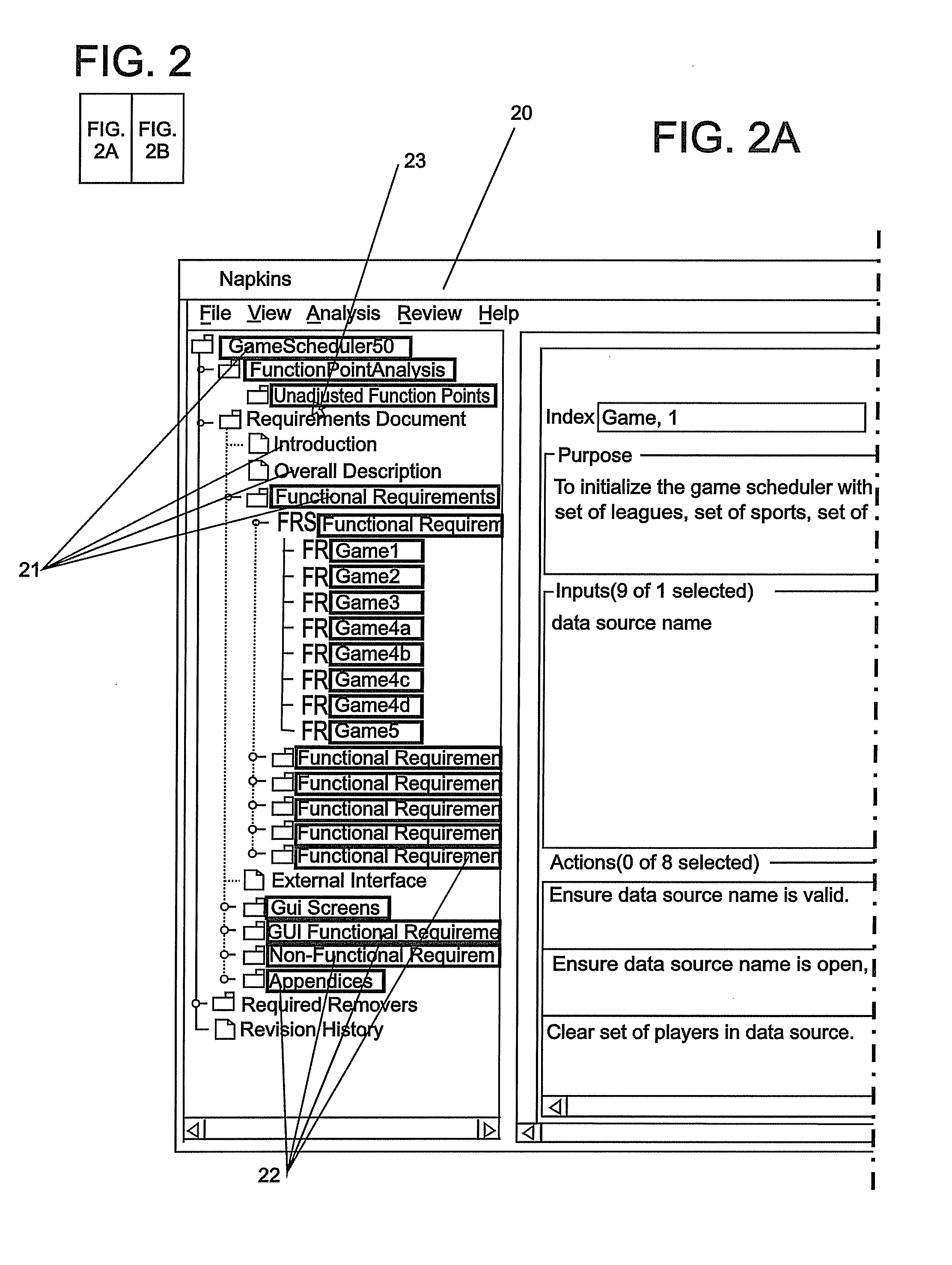
[0011]Further disclosed is a computer program product stored on machine-readable media, the product including machine executable instructions for incorporation into another application as supplemental program code and for tracking a defect during development of a software work product, the computer program product including instructions for displaying the defect in a listing; identifying a component of the work product including the defect by at least one of highlighting, font color changing, and flashing; displaying information related to the defect wherein the information is displayed in at least one of a text box, a list, and a drop-down box wherein the displaying information is a result of pointing to the component; and receiving input rela

Problems solved by technology

Modern software or computer programs can be complicated particularly when the software includes a graphical user interface (GUI).
Each interaction provides an opportunity for the software to fail.
When the software fails, it is referred to as a “defect.” When first written, complicated software can have many defects.
Testing complicated software can also be complicated.
The iterative process can also be complicated and have many opportunities for confusion when testing complicated software.
However, Rational Function Tester does not indicate where a fix was created in the computer program, so it can be inefficient to test the fixes if the software developer does not know which component contains the fix.
Using software to write a test plan can also be complicated when there are many defects to be tested.
Toggling between the two applications requires additional time and can also add to inefficiency and cause mistakes.

Method used


Image

  • Testing framework to highlight functionality component changes
  • Testing framework to highlight functionality component changes
  • Testing framework to highlight functionality component changes

Examples


Embodiment Construction

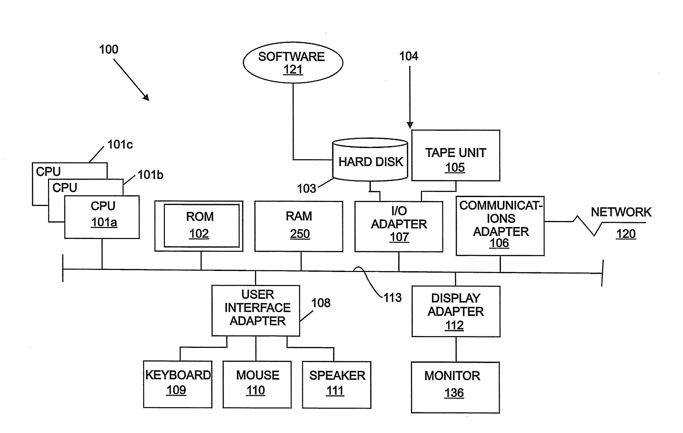
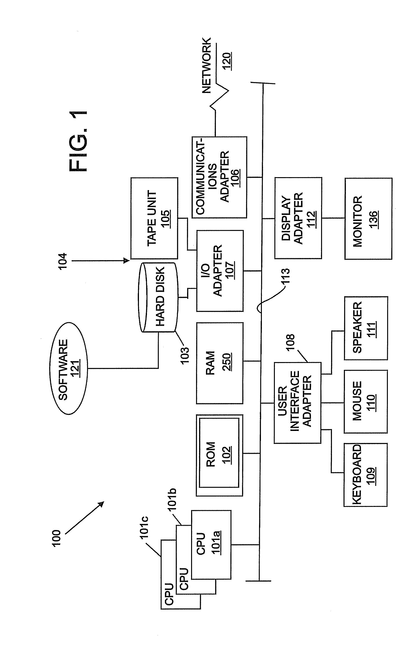
[0021]The teachings are based on an iterative process for software development. Generally, in the prior art, a software developer writes software and documents defects and associated fixes. A software tester tests the software using information related to the defects and the associated fixes documented by the software developer. The software tester documents if each fix was successfully tested. The software developer receives information related to the fixes that were not successfully tested. Using the information, the software developer provides another fix for the defect to complete one iteration of the process.

[0022]The teachings provide an integrated software application or framework for developing and testing a computer program. After the computer program is successfully tested, the computer program may be removed from the application for distribution to a user. Using the application is discussed next.

[0023]A software developer will use the application to identify which compone...


PUM


Abstract

A computer program product stored on machine-readable media, the product including machine executable instructions for tracking a defect during development of a software work product, the computer program product including instructions for displaying the defect; identifying a component of the work product including the defect; displaying information related to the defect; and receiving input related to testing of the defect to update tracking information.

Description

TRADEMARKS[0001]IBM® is a registered trademark of International Business Machines Corporation, Armonk, N.Y., U.S.A. Other names used herein may be registered trademarks, trademarks or product names of International Business Machines Corporation or other companies.BACKGROUND OF THE INVENTION[0002]1. Field of the Invention[0003]This invention relates to the field of software development and particularly to tracking defects during software development.[0004]2. Description of the Related Art[0005]Modern software or computer programs can be complicated particularly when the software includes a graphical user interface (GUI). In order to help simplify writing the software, various software components are used. The various software components generally interact with each other in some way. Each interaction provides an opportunity for the software to fail. When the software fails, it is referred to as a “defect.” When first written, complicated software can have many defects. Testing compli...

Claims


Application Information

Patent Timeline
IPC IPC(8): G06F9/44
CPCG06F11/3688G06F11/366
Inventor GARBERS, BENJAMIN R.KIRKLAND, DUANE D.PETERSON, DALE A.
Owner IBM CORP
Why Eureka
Eureka Blog
Learn More