Flying roller hemming anvil process

a technology of hemming anvil and flying roller, which is applied in the direction of gripping heads, metal-working devices, program-controlled manipulators, etc., can solve the problem of limiting the flexibility of the hemming process

Active Publication Date: 2009-02-12
HIROTEC AMERICA
View PDF2 Cites 39 Cited by
  • Summary
  • Abstract
  • Description
  • Claims
  • Application Information

AI Technical Summary

Benefits of technology

[0006]The present invention provides a roller hemming system and method that includes an anvil robot that mounts a lightweight hemming anvil, a workpiece to be hemmed such as a vehicle closure assembly, and a clamping spider. The anvil robot thereby eliminates the need for a separate part tra

Problems solved by technology

Also, due to the disposition of the anvil, when a set of nested metal panels is positioned on the anvil for hemming, an outer panel of t

Method used


Image

  • Flying roller hemming anvil process
  • Flying roller hemming anvil process
  • Flying roller hemming anvil process

Examples


Embodiment Construction

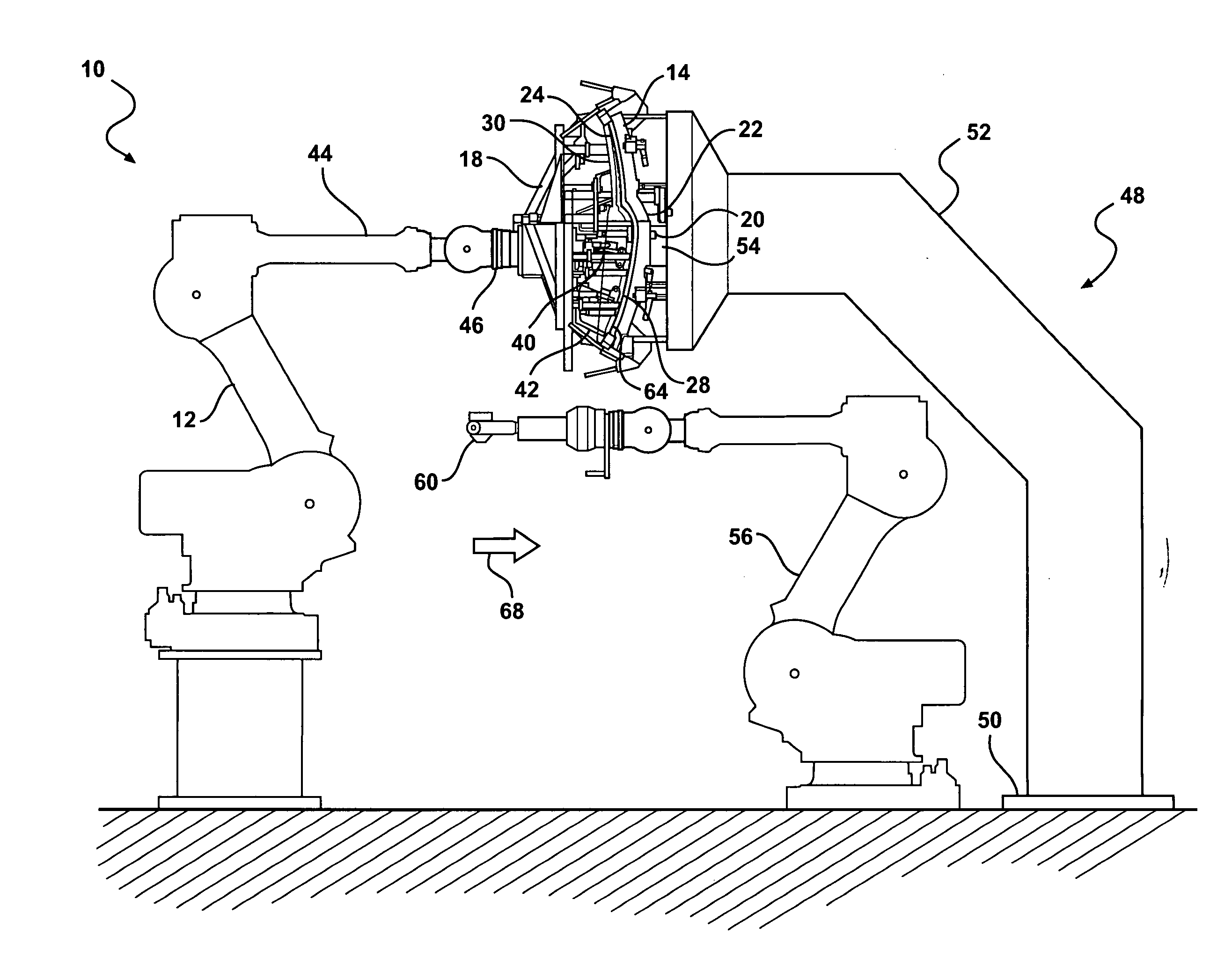
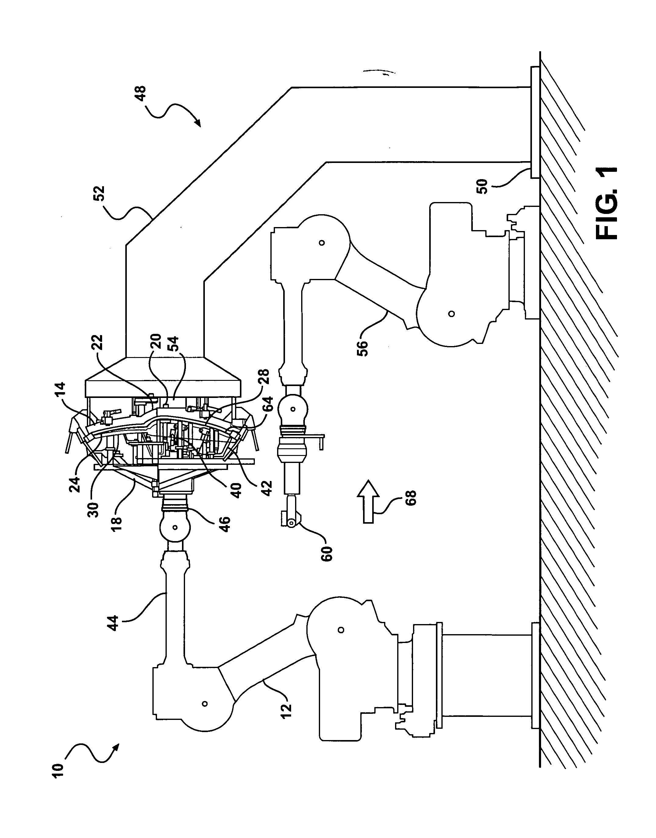
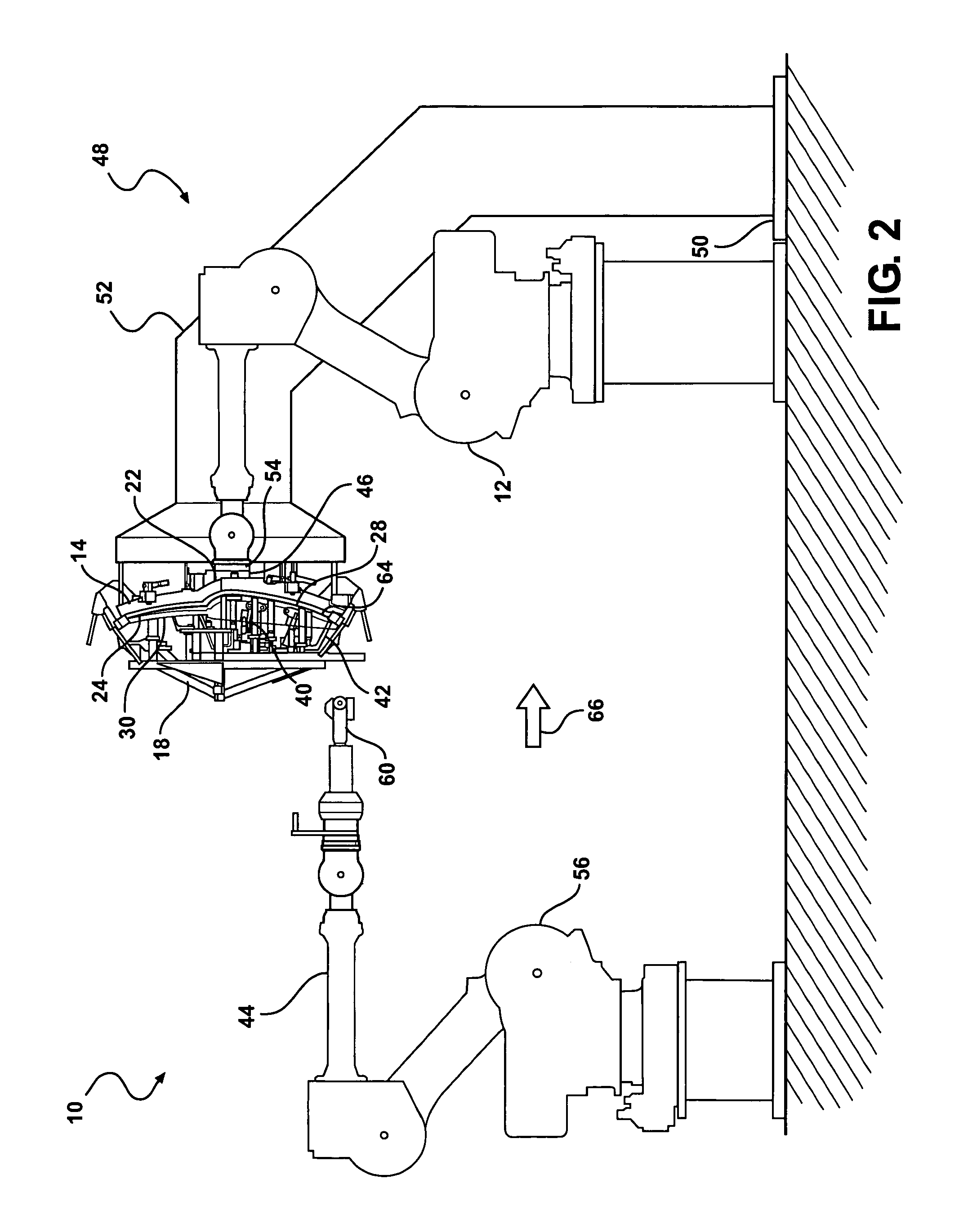
[0024]Referring to the drawing figures, a roller hemming system 10 in accordance with the invention includes an anvil such as a lightweight-hemming anvil 14. The anvil 14 includes a working surface 24 adapted for supporting a workpiece such as a metal panel or set of nested metal panels 30. For example, the workpiece may comprise preformed inner 26 and outer 28 nested metal panels 30 that can be hemmed together to form a vehicle closure assembly such as a door, hood, deck lid, lift gate, or tailgate. The outer panel 28 may be supported against the working surface 24 of the anvil 14 and the inner panel 26 may be located adjacent the outer panel 28 in a nested disposition.

[0025]The hemming system further includes a clamping spider 18. In a closed position, the clamping spider may releasably retain the nested metal panels 30 against the working surface 24 of the anvil 14. For example, the clamping spider 18 may include a plurality of pivotal swing clamps 32 (FIG. 12) that pivot between...


PUM


Abstract

A roller hemming system for edge hemming vehicle closures from nested metal panels includes an anvil robot moveably supporting a hemming anvil having a working surface, a clamping spider cooperable with the anvil robot for clamping the nested metal panels on the working surface, an anvil register including a base and a registration feature for matingly positioning the hemming anvil thereto, a hemming robot including a multi-axis controllable arm, a roller hemming apparatus mounted on a distal end of the multi-axis arm, the roller hemming apparatus being moveable along edges of the nested metal panels on the anvil to hem the panels together.

Description

CROSS REFERENCE TO RELATED APPLICATION[0001]This application claims the priority of U.S. Application No. 60 / 963,590 filed Aug. 6, 2008.TECHNICAL FIELD[0002]This invention relates to robotic roller hemming, and more particularly to a roller hemming system and method including a registerable flying anvil.BACKGROUND OF THE INVENTION[0003]It is known in the art relating to hemming to hem an upturned edge of one or more preformed metal panels to form a hemmed joint or closed panel assembly such as automotive vehicle closure panel assemblies including doors, hoods, deck lids, lift gates, and tailgates.[0004]Conventional roller hemming processes typically require placement of a hemming workpiece into tooling or a fixture anvil having part locating features. For example, a hemming apparatus may be mounted to a multi-axis controllable robot and may include a hem roller carried by a support. The hemming apparatus is adapted for hemming a bent edge portion of the workpiece positioned on the he...

Claims


Application Information

Patent Timeline
IPC IPC(8): B21D7/022B23P11/00
CPCB21D39/021B21D39/023Y10T29/53791B25J11/00B25J15/0019B25J9/0084
Inventor TOENISKOETTER, JAMES B.
Owner HIROTEC AMERICA
Why Eureka
Try Eureka