Computer cooling case of negative pressure sucking type

a technology of negative pressure and cooling case, applied in the computer field, can solve the problems of affecting the cooling/ventilation/heating device, and affecting the operation efficiency of the pc, so as to increase the quantity of fans applied, and avoid the effect of overheating

Inactive Publication Date: 2009-02-12
CHEMTRON RES
View PDF49 Cites 12 Cited by
  • Summary
  • Abstract
  • Description
  • Claims
  • Application Information

AI Technical Summary

Benefits of technology

[0008]The invention is mainly to provide a computer cooling case of negative pressure sucking type. The case may create a negative pressure therein to automatically suck in airflow from the intakes arranged at one side of the case. This airflow may provide a cooling effect to a specific zone in the case, in particular, to the processing chip on a VGA card.

Problems solved by technology

In addition, since most prior cooler structures have been applied to CPU (Central Processing Unit) already, other cooling issues are increasingly emphasized in the current computer elements, such as, VGA card.
In particular, if the heat generated from a graphics chip (e.g. VGA card) is not dissipated, then an overheating problem that influences the PC operation will be probably annoyed.
Because computer case is an almost airtight space and it is uneasy to exhaust heat to the outside, a similar greenhouse effect is often occurred therein to deteriorate the operation efficiency.
However, this solution not only increases the quantity of applying fans, but also creates too much noise because of the increase of using fans.

Method used


Image

  • Computer cooling case of negative pressure sucking type
  • Computer cooling case of negative pressure sucking type
  • Computer cooling case of negative pressure sucking type

Examples


Embodiment Construction

[0018]In cooperation with attached drawings, the technical contents and detailed description of the present invention are described thereinafter according to a preferable embodiment, being not used to limit its executing scope. Any equivalent variation and modification made according to appended claims is all covered by the claims claimed by the present invention.

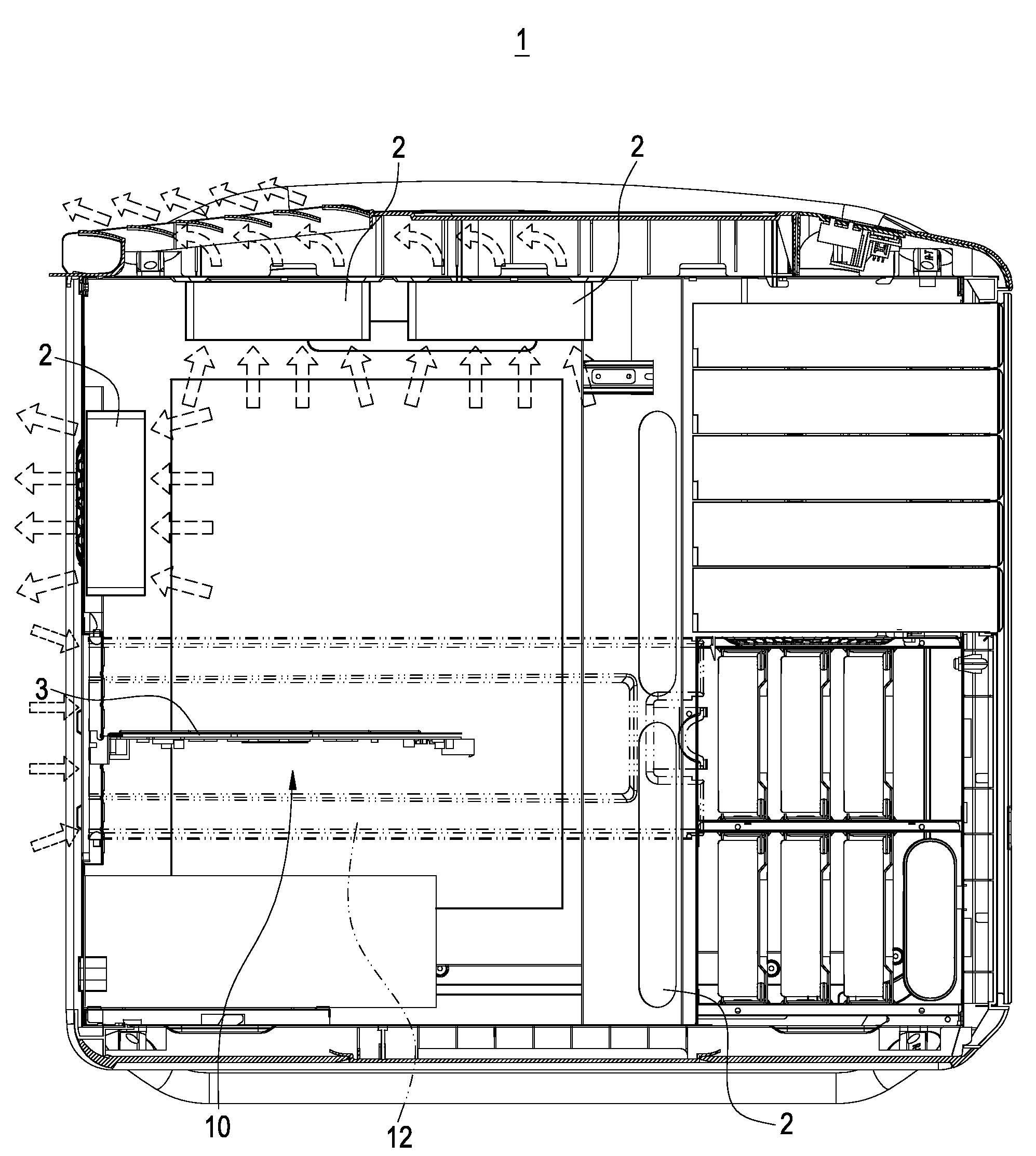
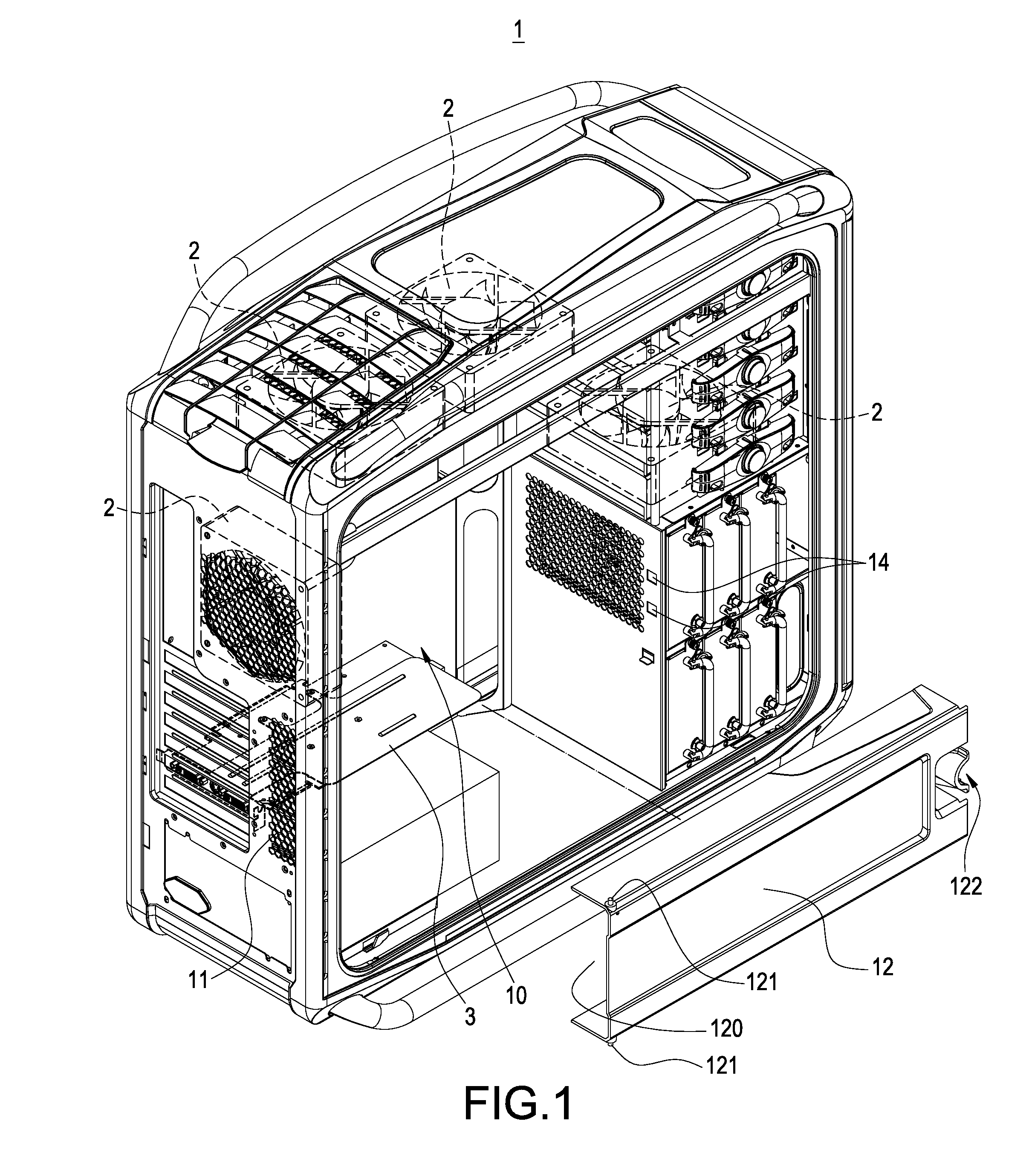
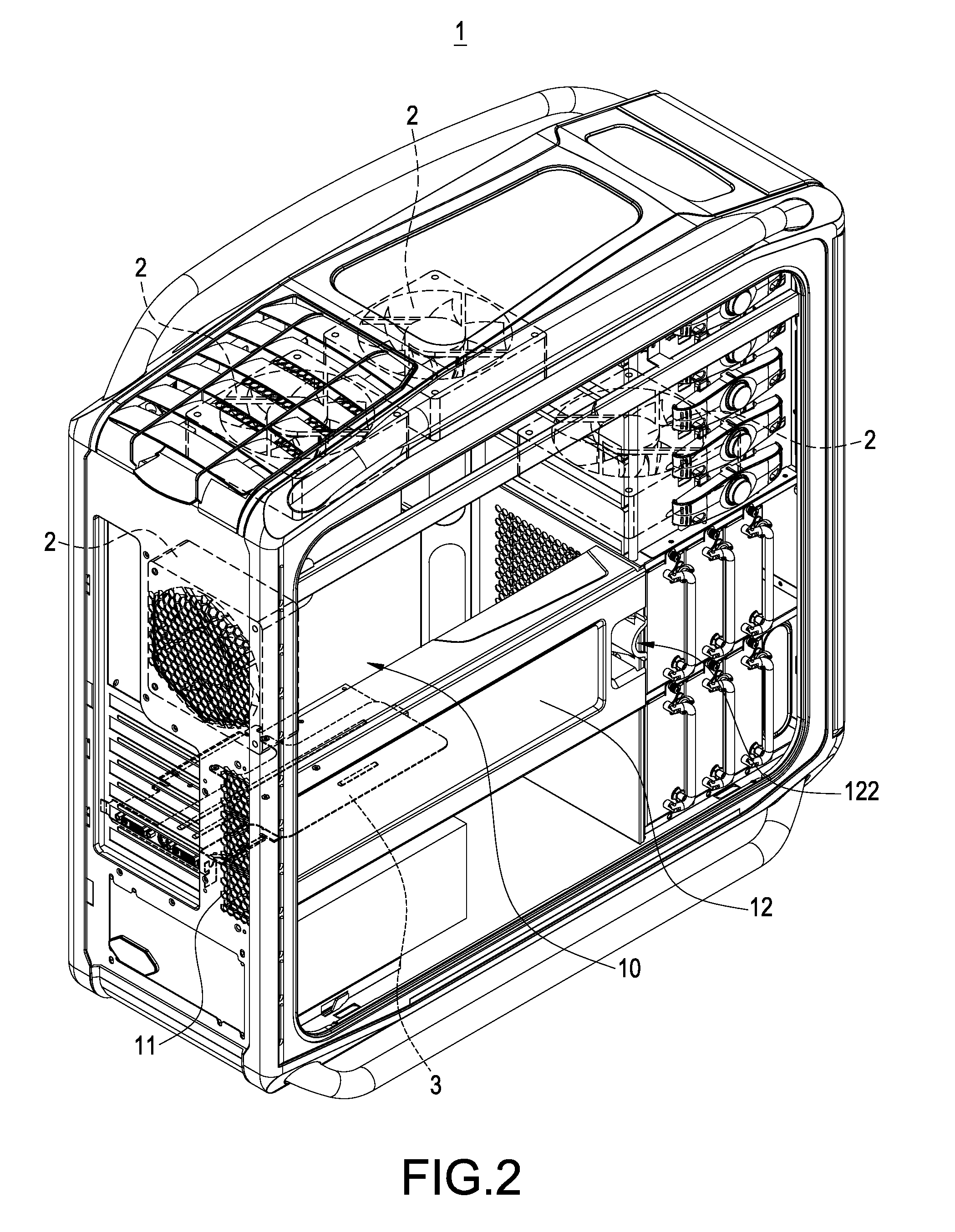
[0019]Please refer to FIG. 1 and FIG. 2, which respectively are an explosive illustration and an assembled illustration of the case interior of the present invention. The invention is mainly to provide a computer cooling case of negative pressure sucking type, which includes a plurality of fans 2, each of which is arranged on a computer case 1 and adopts air-sucking type (i.e., from the outside to the inside) to thereby exhausting the air in the computer case 1 to the ambience. Since a negative pressure is formed in the computer case 1, outside air may be guided to the object to be cooled, for example, the processing chip o...


PUM


Abstract

A computer cooling case includes a computer case and a plurality of fans. Each fan is for exhausting air in the computer case to the outside. During operation, a negative pressure is created in the computer case to define a zone to be cooled. A plurality of intakes are arranged on one side of the computer case in the neighborhood of the zone to be cooled. An air-guiding passage is arranged from each intake to the zone to be cooled. When each fan is operated, since the computer case is under a negative pressure state, outside air may be sucked in through each intake and then guided to each zone to be cooled for undertaking a cooling process.

Description

BACKGROUND OF THE INVENTION[0001]1. Field of the Invention[0002]The present invention generally relates to a computer, in particular, to a case of host computer, which can provide a further cooling function.[0003]2. Description of Prior Art[0004]Following the progress of technology, the executing speed of computer becomes faster and faster, making the temperature generated in a host computer become higher and higher. In order to dissipate the heat generated in the host computer to keep each element therein operated under tolerable temperature, cooler with large size is usually attached onto highly heat-dissipating element for undergoing a cooling effect.[0005]In addition, since most prior cooler structures have been applied to CPU (Central Processing Unit) already, other cooling issues are increasingly emphasized in the current computer elements, such as, VGA card. Besides, since current computer all needs the operational support of multimedia and due to a rise in game software, the...

Claims


Application Information

Patent Timeline
Patent Type & Authority Applications(United States)
IPC IPC(8): F28F13/12H05K7/20
CPCG06F1/20
Inventor CHEN, YUNG-HAO
Owner CHEMTRON RES
Why Eureka
Try Eureka